

568
Practical MATLAB
® Applications for Engineers
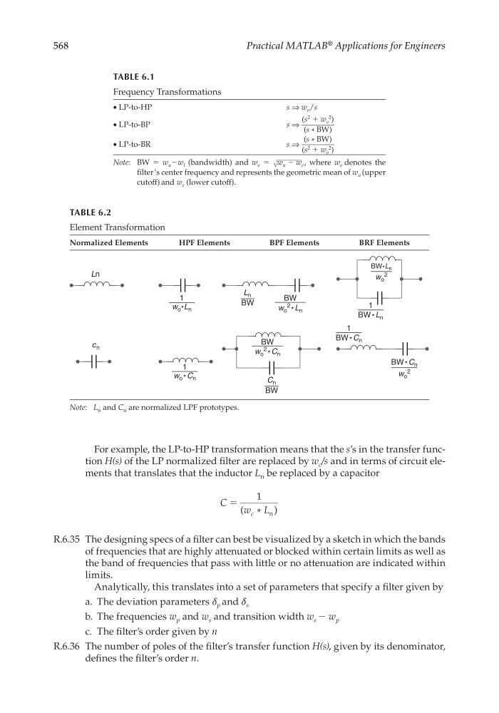
For example, the LP-to-HP transformation means that the s’s in the transfer function H(s) of the LP normalized fi lter are replaced by w c /s and in terms of circuit elements that translates that the inductor L n be replaced by a capacitor
C
w L
c
ϭ
1
(
)
n
*
R.6.35 The designing specs of a fi lter can best be visualized by a sketch in which the bands
of frequencies that are highly attenuated or blocked within certain limits as well as
the band of frequencies that pass with little or no attenuation are indicated within
limits.
Analytically, this translates into a set of parameters that specify a fi lter given by
a. The deviation parameters δ p and δ s
b. The frequencies w p and w s and transition width w s − w p
c. The fi lter’s order given by n
R.6.36 The number of poles of the fi lter’s transfer function H(s), given by its denominator,
defi nes the fi lter’s order n.
TABLE 6.1
Frequency Transformations
• LP-to-HP
s ⇒ w o /s
• LP-to-BP
s ⇒
(s
2 + w o
2 )
_________
(s * BW)
• LP-to-BR
s ⇒
(s * BW)
_________
(s
2 + w o
2 )
Note: BW = w u −w l (bandwidth) and w o = √
_______
w u – w e , where w o denotes the
fi lter’s center frequency and represents the geometric mean of w u (upper
cutoff) and w e (lower cutoff).
TABLE 6.2
Element Transformation
Normalized Elements
HPF Elements
BPF Elements
BRF Elements
Ln
w o* L n
BW
BW
w o
2 * L n
BW * L n
c n
BW * C n
1
w o* C n
1
1
1
w o
2
BW * C n
L n
BW
C n
BW
w o
2 * C n
BW * L n
w o
2
Note: L n and C n are normalized LPF prototypes.
CRC_47760_CH006.indd 568
CRC_47760_CH006.indd 568
7/23/2008 2:26:31 PM
7/23/2008 2:26:31 PM