

566
Practical MATLAB
® Applications for Engineers
R.6.25 The design of any of the fi lters defi ned in R.6.22 is accomplished by fi rst designing
a normalized LPF prototype. A normalized LPF is a fi lter with a cutoff frequency
of w p = 1 rad/s connected to a load of R = 1 Ω.
R.6.26 The normalized LPF will be implemented employing electrical elements using
the notations R n , L n , and C n (referred to as normalized resistors, inductors, and
capacitors).
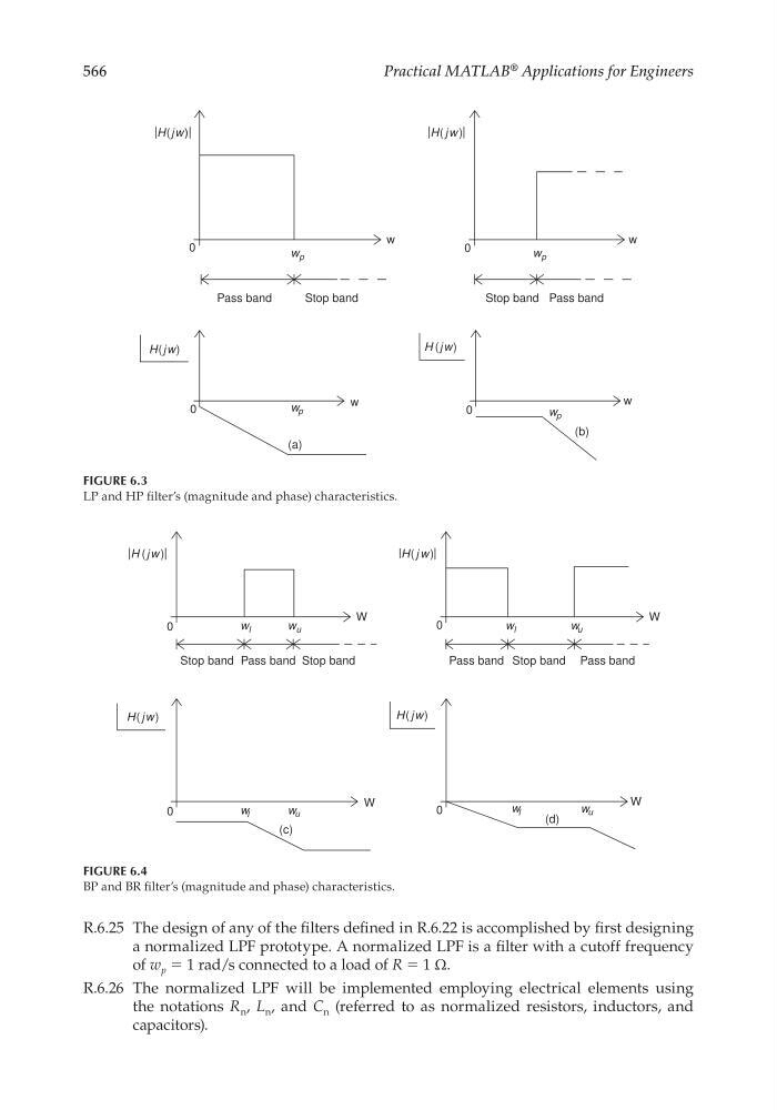
FIGURE 6.3
LP and HP fi lter’s (magnitude and phase) characteristics.
Pass band
Stop band
0
0
0
0
w p
w
|H(jw)|
H(jw)
Pass band
Stop band
w p
w
|H( jw )|
(b)
w p
w
H (jw)
(a)
w p
w
FIGURE 6.4
BP and BR fi lter’s (magnitude and phase) characteristics.
Pass band
Stop band
Stop band
0
w l
w u
w l
w u
w l
w u
W
|H ( jw )|
Pass band
Pass band
Stop band
0
w l
w u
W
|H( j w)|
(d)
0
W
H ( jw)
(c)
0
W
H( jw)
CRC_47760_CH006.indd 566
CRC_47760_CH006.indd 566
7/23/2008 2:26:25 PM
7/23/2008 2:26:25 PM