

316
Practical MATLAB
® Applications for Engineers
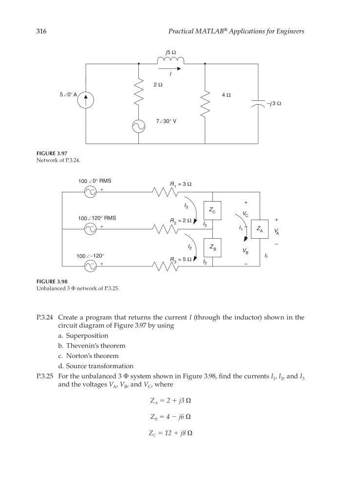
P.3.24 Create a program that returns the current I (through the inductor) shown in the
circuit diagram of Figure 3.97 by using
a. Superposition
b. Thevenin’s theorem
c. Norton’s theorem
d. Source transformation
P.3.25 For the unbalanced 3 Φ system shown in Figure 3.98, fi nd the currents I 1 , I 2 , and I 3
and the voltages V A , V B , and V C , where
Z A = 2 + j3
Z B = 4 − j6
Z C = 12 + j8
I
5
–j 3 Ω
4 Ω
7 30° V
2 Ω
j5 Ω
0° A
FIGURE 3.97
Network of P.3.24.
+
−
+
−
+
−
100 0° RMS
R 1 = 3 Ω
R 2 = 2 Ω
R 3 = 5 Ω
I 3
I 1
I 3
I 2
I 2
Z C
Z B
Z A
+
V C
–
+
V B
–
+
V A
–
I 1
100 120° RMS
100 −120°
FIGURE 3.98
Unbalanced 3 Φ network of P.3.25.
CRC_47760_CH003.indd 316
CRC_47760_CH003.indd 316
7/23/2008 1:27:56 PM
7/23/2008 1:27:56 PM
Practical MATLAB
® Applications for Engineers
P.3.24 Create a program that returns the current I (through the inductor) shown in the
circuit diagram of Figure 3.97 by using
a. Superposition
b. Thevenin’s theorem
c. Norton’s theorem
d. Source transformation
P.3.25 For the unbalanced 3 Φ system shown in Figure 3.98, fi nd the currents I 1 , I 2 , and I 3
and the voltages V A , V B , and V C , where
Z A = 2 + j3
Z B = 4 − j6
Z C = 12 + j8
I
5
–j 3 Ω
4 Ω
7 30° V
2 Ω
j5 Ω
0° A
FIGURE 3.97
Network of P.3.24.
+
−
+
−
+
−
100 0° RMS
R 1 = 3 Ω
R 2 = 2 Ω
R 3 = 5 Ω
I 3
I 1
I 3
I 2
I 2
Z C
Z B
Z A
+
V C
–
+
V B
–
+
V A
–
I 1
100 120° RMS
100 −120°
FIGURE 3.98
Unbalanced 3 Φ network of P.3.25.
CRC_47760_CH003.indd 316
CRC_47760_CH003.indd 316
7/23/2008 1:27:56 PM
7/23/2008 1:27:56 PM