

Alternating Current Analysis
239
v(t)
I L sin t
I
C
sin( t)
m
ϭ Ϫ
ϩ
m
( )
or
v(t) = XI m cos(t + θ)
where the total reactance is X = ωL − 1/(ωC).
Observe that the reactance X can be positive or negative. If X > 0, then v(t) =
I m X cos(ωt + π/2) (inductive equivalent), and if X < 0, then v(t) = I m X cos(ωt − π/2)
(capacitive equivalent).
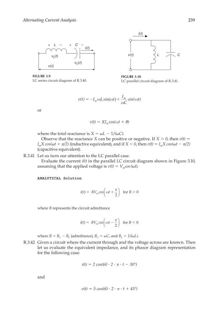
R.3.41 Let us turn our attention to the LC parallel case.
Evaluate the current i(t) in the parallel LC circuit diagram shown in Figure 3.10,
assuming that the applied voltage is v(t) = V m cos (ωt).
ANALYTICAL Solution
i t
BV cos t
B
m
( ) ϭ
ϩ
Ͼ
for
2
0
where B represents the circuit admittance
i t
BV cos t
B
m
( ) ϭ
Ϫ
Ͻ
for
2
0
where B = B C − B L (admittance), B C = ωC, and B L = 1/(ωL).
R.3.42 Given a circuit where the current through and the voltage across are known. Then
let us evaluate the equivalent impedance, and its phasor diagram representation
for the following case:
i(t) = 2 cos(60 ⋅ 2 ⋅ ⋅ t − 30°)
and
v(t) = 5 cos(60 ⋅ 2 ⋅ ⋅ t + 45°)
FIGURE 3.9
LC series circuit diagram of R.3.40.
+ C –
i(t )
v(t )
+ L –
v L (t)
v C (t )
FIGURE 3.10
LC parallel circuit diagram of R.3.41.
i(t)
v (t)
L
C
CRC_47760_CH003.indd 239
CRC_47760_CH003.indd 239
7/23/2008 1:27:33 PM
7/23/2008 1:27:33 PM
239
v(t)
I L sin t
I
C
sin( t)
m
ϭ Ϫ
ϩ
m
( )
or
v(t) = XI m cos(t + θ)
where the total reactance is X = ωL − 1/(ωC).
Observe that the reactance X can be positive or negative. If X > 0, then v(t) =
I m X cos(ωt + π/2) (inductive equivalent), and if X < 0, then v(t) = I m X cos(ωt − π/2)
(capacitive equivalent).
R.3.41 Let us turn our attention to the LC parallel case.
Evaluate the current i(t) in the parallel LC circuit diagram shown in Figure 3.10,
assuming that the applied voltage is v(t) = V m cos (ωt).
ANALYTICAL Solution
i t
BV cos t
B
m
( ) ϭ
ϩ
Ͼ
for
2
0
where B represents the circuit admittance
i t
BV cos t
B
m
( ) ϭ
Ϫ
Ͻ
for
2
0
where B = B C − B L (admittance), B C = ωC, and B L = 1/(ωL).
R.3.42 Given a circuit where the current through and the voltage across are known. Then
let us evaluate the equivalent impedance, and its phasor diagram representation
for the following case:
i(t) = 2 cos(60 ⋅ 2 ⋅ ⋅ t − 30°)
and
v(t) = 5 cos(60 ⋅ 2 ⋅ ⋅ t + 45°)
FIGURE 3.9
LC series circuit diagram of R.3.40.
+ C –
i(t )
v(t )
+ L –
v L (t)
v C (t )
FIGURE 3.10
LC parallel circuit diagram of R.3.41.
i(t)
v (t)
L
C
CRC_47760_CH003.indd 239
CRC_47760_CH003.indd 239
7/23/2008 1:27:33 PM
7/23/2008 1:27:33 PM