

Direct Current and Transient Analysis
221
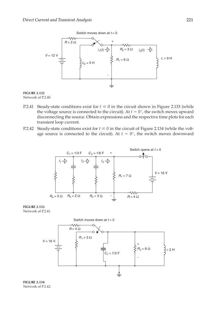
FIGURE 2.132
Network of P.2.40.
V = 12 V
Switch moves down at t = 0
+
−
R = 2 Ω
L = 9 H
R 1 = 6 Ω
R 2 = 3 Ω
L 2 = 5 H
i 2 (t)
i 1 (t )
P.2.41 Steady-state conditions exist for t ≤ 0 in the circuit shown in Figure 2.133 (while
the voltage source is connected to the circuit). At t = 0
+
, the switch moves upward
disconnecting the source. Obtain expressions and the respective time plots for each
transient loop current.
P.2.42 Steady-state conditions exist for t ≤ 0 in the circuit of Figure 2.134 (while the voltage source is connected to the circuit). At t = 0
+
, the switch moves downward
FIGURE 2.133
Network of P.2.41.
V = 16 V
+
−
C 2 = 1/6 F
R = 4 Ω
R 1 = 7 Ω
R 2 = 3 Ω
R 3 = 2 Ω
R 4 = 5 Ω
Switch opens at t = 0
C 1 = 1/3 F
I 3
I 2
I 1
FIGURE 2.134
Network of P.2.42.
V = 16 V
Switch moves down at t = 0
R 2 = 6 Ω
R 1 = 3 Ω
R = 4 Ω
+
−
C 1 = 1/3 F
= 2 H
CRC_47760_CH002.indd 221
CRC_47760_CH002.indd 221
7/23/2008 1:39:05 PM
7/23/2008 1:39:05 PM
221
FIGURE 2.132
Network of P.2.40.
V = 12 V
Switch moves down at t = 0
+
−
R = 2 Ω
L = 9 H
R 1 = 6 Ω
R 2 = 3 Ω
L 2 = 5 H
i 2 (t)
i 1 (t )
P.2.41 Steady-state conditions exist for t ≤ 0 in the circuit shown in Figure 2.133 (while
the voltage source is connected to the circuit). At t = 0
+
, the switch moves upward
disconnecting the source. Obtain expressions and the respective time plots for each
transient loop current.
P.2.42 Steady-state conditions exist for t ≤ 0 in the circuit of Figure 2.134 (while the voltage source is connected to the circuit). At t = 0
+
, the switch moves downward
FIGURE 2.133
Network of P.2.41.
V = 16 V
+
−
C 2 = 1/6 F
R = 4 Ω
R 1 = 7 Ω
R 2 = 3 Ω
R 3 = 2 Ω
R 4 = 5 Ω
Switch opens at t = 0
C 1 = 1/3 F
I 3
I 2
I 1
FIGURE 2.134
Network of P.2.42.
V = 16 V
Switch moves down at t = 0
R 2 = 6 Ω
R 1 = 3 Ω
R = 4 Ω
+
−
C 1 = 1/3 F
= 2 H
CRC_47760_CH002.indd 221
CRC_47760_CH002.indd 221
7/23/2008 1:39:05 PM
7/23/2008 1:39:05 PM