

218
Practical MATLAB
® Applications for Engineers
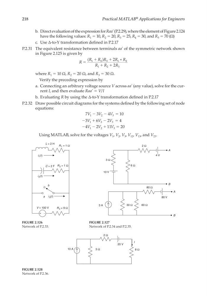
FIGURE 2.126
Network of P.2.33.
b
V = 100 V
L = 2 H
R 3 = 9 Ω
R 2 = 1 Ω
R 1 = 1 Ω
a i 3 (t)
i 2 (t)
i 1 (t)
C = 2 F
+ −
FIGURE 2.127
Network of P.2.34 and P.2.35.
80 Ω
3 A
30 Ω
3 Ω
6 Ω
2 Ω
4 V
10 V
60 Ω
80 V
A
B
A
B
FIGURE 2.128
Network of P.2.36.
10 A
2 Ω
8 Ω
3 Ω
20 V
I
b. Direct evaluation of the expression for Raa’ (P.2.29), where the element of Figure 2.124
have the following values: R 1 = 10, R 2 = 20, R 3 = 25, R 4 = 30, and R 5 = 70 (Ω)
c. Use ∆-to-Y transformation defi ned in P.2.17
P.2.31 The equivalent resistance between terminals aa’ of the symmetric network shown
in Figure 2.125 is given by
R
R
R R
R R
R
R
R
ϭ
ϩ
ϩ
ϩ ϩ
(
)
*
1
2
3
1
2
1
2
3
2
2
where R 1 = 10 Ω, R 2 = 20 Ω, and R 3 = 30 Ω.
Verify the preceding expression by
a. Connecting an arbitrary voltage source V across aa’ (any value), solve for the current I, and then evaluate Raa’ = V/I
b. Evaluating R by using the ∆-to-Y transformation defi ned in P.2.17
P.2.32 Draw possible circuit diagrams for the systems defi ned by the following set of node
equations:
7
3
4
10
3
6
2
4
4
2
11
20
1
2
3
1
2
3
1
2
3
V
V
V
V
V
V
V
V
V
Ϫ
Ϫ
Ϫ
Ϫ
Ϫ
Ϫ
ϭ
ϩ
ϭ
ϩ
ϭ
Using MATLAB, solve for the voltages V 1 , V 2 , V 3 , V 12 , V 13 , and V 23 .
CRC_47760_CH002.indd 218
CRC_47760_CH002.indd 218
7/23/2008 1:39:05 PM
7/23/2008 1:39:05 PM
Practical MATLAB
® Applications for Engineers
FIGURE 2.126
Network of P.2.33.
b
V = 100 V
L = 2 H
R 3 = 9 Ω
R 2 = 1 Ω
R 1 = 1 Ω
a i 3 (t)
i 2 (t)
i 1 (t)
C = 2 F
+ −
FIGURE 2.127
Network of P.2.34 and P.2.35.
80 Ω
3 A
30 Ω
3 Ω
6 Ω
2 Ω
4 V
10 V
60 Ω
80 V
A
B
A
B
FIGURE 2.128
Network of P.2.36.
10 A
2 Ω
8 Ω
3 Ω
20 V
I
b. Direct evaluation of the expression for Raa’ (P.2.29), where the element of Figure 2.124
have the following values: R 1 = 10, R 2 = 20, R 3 = 25, R 4 = 30, and R 5 = 70 (Ω)
c. Use ∆-to-Y transformation defi ned in P.2.17
P.2.31 The equivalent resistance between terminals aa’ of the symmetric network shown
in Figure 2.125 is given by
R
R
R R
R R
R
R
R
ϭ
ϩ
ϩ
ϩ ϩ
(
)
*
1
2
3
1
2
1
2
3
2
2
where R 1 = 10 Ω, R 2 = 20 Ω, and R 3 = 30 Ω.
Verify the preceding expression by
a. Connecting an arbitrary voltage source V across aa’ (any value), solve for the current I, and then evaluate Raa’ = V/I
b. Evaluating R by using the ∆-to-Y transformation defi ned in P.2.17
P.2.32 Draw possible circuit diagrams for the systems defi ned by the following set of node
equations:
7
3
4
10
3
6
2
4
4
2
11
20
1
2
3
1
2
3
1
2
3
V
V
V
V
V
V
V
V
V
Ϫ
Ϫ
Ϫ
Ϫ
Ϫ
Ϫ
ϭ
ϩ
ϭ
ϩ
ϭ
Using MATLAB, solve for the voltages V 1 , V 2 , V 3 , V 12 , V 13 , and V 23 .
CRC_47760_CH002.indd 218
CRC_47760_CH002.indd 218
7/23/2008 1:39:05 PM
7/23/2008 1:39:05 PM