

Direct Current and Transient Analysis
137
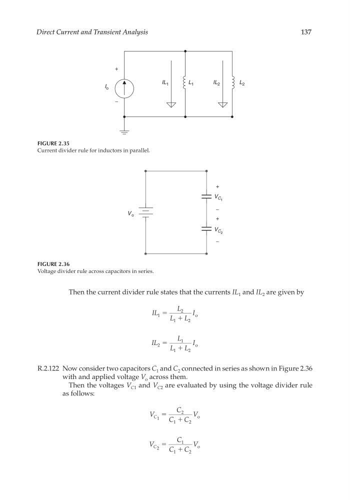
Then the current divider rule states that the currents IL 1 and IL 2 are given by
IL
L
L
L
I
1
2
1
2
ϭ ϩ
o
IL
L
L
L
I
2
1
1
2
ϭ ϩ
o
R.2.122 Now consider two capacitors C 1 and C 2 connected in series as shown in Figure 2.36
with and applied voltage V o across them.
Then the voltages V C1 and V C2 are evaluated by using the voltage divider rule
as follows:
V
C
C
C
V
C 1
o
ϭ
ϩ
2
1
2
V
C
C
C
V
C 2
o
ϭ
ϩ
1
1
2
FIGURE 2.35
Current divider rule for inductors in parallel.
I o
+
−
IL 1
IL 2
L 2
L 1
FIGURE 2.36
Voltage divider rule across capacitors in series.
V o
V C 1
V C 2
+
−
+
−
CRC_47760_CH002.indd 137
CRC_47760_CH002.indd 137
7/23/2008 1:38:44 PM
7/23/2008 1:38:44 PM
137
Then the current divider rule states that the currents IL 1 and IL 2 are given by
IL
L
L
L
I
1
2
1
2
ϭ ϩ
o
IL
L
L
L
I
2
1
1
2
ϭ ϩ
o
R.2.122 Now consider two capacitors C 1 and C 2 connected in series as shown in Figure 2.36
with and applied voltage V o across them.
Then the voltages V C1 and V C2 are evaluated by using the voltage divider rule
as follows:
V
C
C
C
V
C 1
o
ϭ
ϩ
2
1
2
V
C
C
C
V
C 2
o
ϭ
ϩ
1
1
2
FIGURE 2.35
Current divider rule for inductors in parallel.
I o
+
−
IL 1
IL 2
L 2
L 1
FIGURE 2.36
Voltage divider rule across capacitors in series.
V o
V C 1
V C 2
+
−
+
−
CRC_47760_CH002.indd 137
CRC_47760_CH002.indd 137
7/23/2008 1:38:44 PM
7/23/2008 1:38:44 PM