

128
Practical MATLAB
® Applications for Engineers
solving for i(t) results in
i t
V
R
e
t
L
R
t
( )
(
)
/
ϭ
Ն
ϭ
1 Ϫ
Ϫ τ
for
0 with
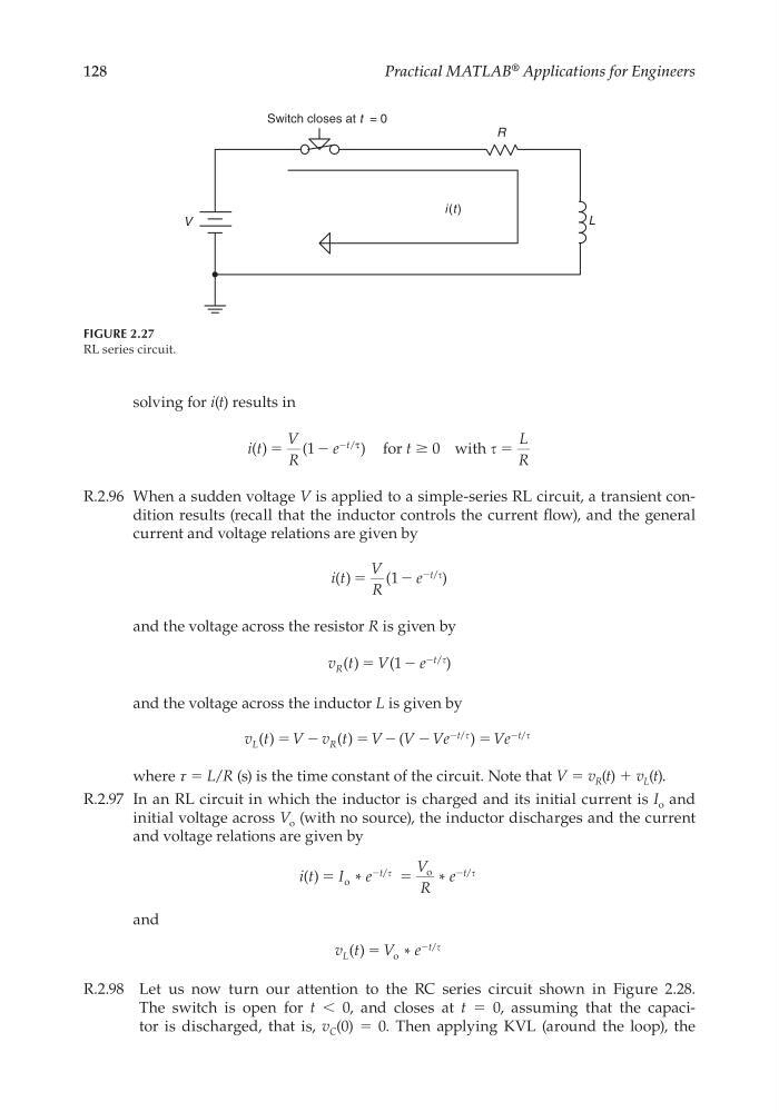
R.2.96 When a sudden voltage V is applied to a simple-series RL circuit, a transient condition results (recall that the inductor controls the current fl ow), and the general
current and voltage relations are given by
i t
V
R
e
t
( ) ϭ (
)
/
1 Ϫ
Ϫ
and the voltage across the resistor R is given by
v t
V
e
R
t
( )
(
)
/
ϭ 1 Ϫ
Ϫ
and the voltage across the inductor L is given by
v t
V v t
V V Ve
Ve
L
R
t
t
( )
( )
(
)
/
/
ϭ
ϭ
ϭ
Ϫ
Ϫ
Ϫ
Ϫ Ϫ
where τ = L/R (s) is the time constant of the circuit. Note that V = v R (t) + v L (t).
R.2.97 In an RL circuit in which the inductor is charged and its initial current is I o and
initial voltage across V o (with no source), the inductor discharges and the current
and voltage relations are given by
i t
I e
V
R
e
t
t
( )
*
*
/
/
ϭ
ϭ
o
o
Ϫ
Ϫ
and
v t
V e
L
t
( )
*
/
ϭ o
Ϫ
R.2.98 Let us now turn our attention to the RC series circuit shown in Figure 2.28.
The switch is open for t < 0, and closes at t = 0, assuming that the capacitor is discharged, that is, v C (0) = 0. Then applying KVL (around the loop), the
FIGURE 2.27
RL series circuit.
V
R
L
Switch closes at t = 0
i (t )
CRC_47760_CH002.indd 128
CRC_47760_CH002.indd 128
7/23/2008 1:38:42 PM
7/23/2008 1:38:42 PM
Practical MATLAB
® Applications for Engineers
solving for i(t) results in
i t
V
R
e
t
L
R
t
( )
(
)
/
ϭ
Ն
ϭ
1 Ϫ
Ϫ τ
for
0 with
R.2.96 When a sudden voltage V is applied to a simple-series RL circuit, a transient condition results (recall that the inductor controls the current fl ow), and the general
current and voltage relations are given by
i t
V
R
e
t
( ) ϭ (
)
/
1 Ϫ
Ϫ
and the voltage across the resistor R is given by
v t
V
e
R
t
( )
(
)
/
ϭ 1 Ϫ
Ϫ
and the voltage across the inductor L is given by
v t
V v t
V V Ve
Ve
L
R
t
t
( )
( )
(
)
/
/
ϭ
ϭ
ϭ
Ϫ
Ϫ
Ϫ
Ϫ Ϫ
where τ = L/R (s) is the time constant of the circuit. Note that V = v R (t) + v L (t).
R.2.97 In an RL circuit in which the inductor is charged and its initial current is I o and
initial voltage across V o (with no source), the inductor discharges and the current
and voltage relations are given by
i t
I e
V
R
e
t
t
( )
*
*
/
/
ϭ
ϭ
o
o
Ϫ
Ϫ
and
v t
V e
L
t
( )
*
/
ϭ o
Ϫ
R.2.98 Let us now turn our attention to the RC series circuit shown in Figure 2.28.
The switch is open for t < 0, and closes at t = 0, assuming that the capacitor is discharged, that is, v C (0) = 0. Then applying KVL (around the loop), the
FIGURE 2.27
RL series circuit.
V
R
L
Switch closes at t = 0
i (t )
CRC_47760_CH002.indd 128
CRC_47760_CH002.indd 128
7/23/2008 1:38:42 PM
7/23/2008 1:38:42 PM