

Direct Current and Transient Analysis
119
currents or voltages produced independently by each source (current or voltage).
The concept of independence means that only one source is considered active,
whereas all the other sources (voltage or current) are set to zero.
Recall that when a voltage source is set to zero, the source can be replaced by a
short circuit, and similarly, when a current source is set to zero, the source can be
replaced by an open circuit.
The superposition theorem states then that in an n source electrical network, the
current through or the voltage drop across any arbitrary network element can be
obtained by solving n single source networks (where the single source network
refers to the original network with only one source at the time whereas all the
remaining sources are set to zero) for the variable of interest, which can be a current or a voltage. The solution is the algebraic sum of the partial solutions (of the
single source networks).
Note that the voltage and current polarities (directions) are important when
solving each single source network, since the solution is the algebraic sum of the
(solutions) contribution of each source.
R.2.79 Thevenin’s theorem states that any two-terminal linear DC network across a load
R L can be replaced by two elements: a voltage source called the Thevenin voltage V TH and a resistor placed in series called the Thevenin resistance R TH . The
Thevenin resistance R TH is calculated by setting all the sources to zero, removing
the arbitrary load R L (replace it by an open), labeling its terminals aa’, and either
calculating or measuring the resistance looking into the terminals (aa’).
The Thevenin voltage V TH is the open-circuit voltage across terminals aa’, after
having removed the arbitrary load R L from the original circuit, while preserving
all the sources.
R.2.80 Norton’s theorem states that any two-terminal linear DC network can be replaced
by two elements, a current source in parallel with a resistor, where the current
source is the Norton short-circuit current denoted by I N , and the resistance is the
Thevenin resistance R TH .
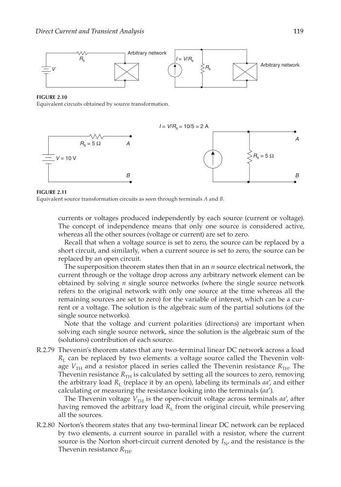
FIGURE 2.10
Equivalent circuits obtained by source transformation.
R s
I = V/R s
Arbitrary network
Arbitrary network
V
R s
FIGURE 2.11
Equivalent source transformation circuits as seen through terminals A and B.
R s = 5 Ω
R s = 5 Ω
I = V/R s = 10/5 = 2 A
V = 10 V
A
B
A
B
CRC_47760_CH002.indd 119
CRC_47760_CH002.indd 119
7/23/2008 1:38:39 PM
7/23/2008 1:38:39 PM
119
currents or voltages produced independently by each source (current or voltage).
The concept of independence means that only one source is considered active,
whereas all the other sources (voltage or current) are set to zero.
Recall that when a voltage source is set to zero, the source can be replaced by a
short circuit, and similarly, when a current source is set to zero, the source can be
replaced by an open circuit.
The superposition theorem states then that in an n source electrical network, the
current through or the voltage drop across any arbitrary network element can be
obtained by solving n single source networks (where the single source network
refers to the original network with only one source at the time whereas all the
remaining sources are set to zero) for the variable of interest, which can be a current or a voltage. The solution is the algebraic sum of the partial solutions (of the
single source networks).
Note that the voltage and current polarities (directions) are important when
solving each single source network, since the solution is the algebraic sum of the
(solutions) contribution of each source.
R.2.79 Thevenin’s theorem states that any two-terminal linear DC network across a load
R L can be replaced by two elements: a voltage source called the Thevenin voltage V TH and a resistor placed in series called the Thevenin resistance R TH . The
Thevenin resistance R TH is calculated by setting all the sources to zero, removing
the arbitrary load R L (replace it by an open), labeling its terminals aa’, and either
calculating or measuring the resistance looking into the terminals (aa’).
The Thevenin voltage V TH is the open-circuit voltage across terminals aa’, after
having removed the arbitrary load R L from the original circuit, while preserving
all the sources.
R.2.80 Norton’s theorem states that any two-terminal linear DC network can be replaced
by two elements, a current source in parallel with a resistor, where the current
source is the Norton short-circuit current denoted by I N , and the resistance is the
Thevenin resistance R TH .
FIGURE 2.10
Equivalent circuits obtained by source transformation.
R s
I = V/R s
Arbitrary network
Arbitrary network
V
R s
FIGURE 2.11
Equivalent source transformation circuits as seen through terminals A and B.
R s = 5 Ω
R s = 5 Ω
I = V/R s = 10/5 = 2 A
V = 10 V
A
B
A
B
CRC_47760_CH002.indd 119
CRC_47760_CH002.indd 119
7/23/2008 1:38:39 PM
7/23/2008 1:38:39 PM