

Direct Current and Transient Analysis
111
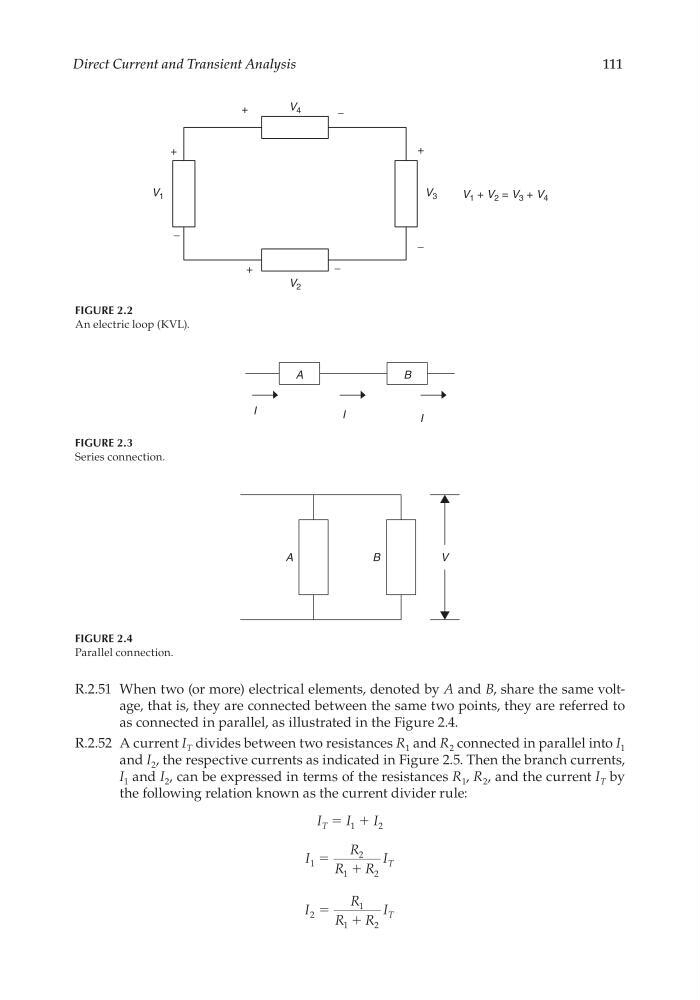
R.2.51 When two (or more) electrical elements, denoted by A and B, share the same voltage, that is, they are connected between the same two points, they are referred to
as connected in parallel, as illustrated in the Figure 2.4.
R.2.52 A current I T divides between two resistances R 1 and R 2 connected in parallel into I 1
and I 2 , the respective currents as indicated in Figure 2.5. Then the branch currents,
I 1 and I 2 , can be expressed in terms of the resistances R 1 , R 2 , and the current I T by
the following relation known as the current divider rule:
I T = I 1 + I 2
I
R
R
R
I T
1
2
1
2
ϭ
ϩ
I
R
R
R
I T
2
1
1
2
ϭ
ϩ
FIGURE 2.2
An electric loop (KVL).
V 1 + V 2 = V 3 + V 4
+
V 3
−
+
+
+
−
V 2
V 4
−
−
V 1
FIGURE 2.3
Series connection.
A
B
I
I
I
FIGURE 2.4
Parallel connection.
A
B
V
CRC_47760_CH002.indd 111
CRC_47760_CH002.indd 111
7/23/2008 1:38:36 PM
7/23/2008 1:38:36 PM
111
R.2.51 When two (or more) electrical elements, denoted by A and B, share the same voltage, that is, they are connected between the same two points, they are referred to
as connected in parallel, as illustrated in the Figure 2.4.
R.2.52 A current I T divides between two resistances R 1 and R 2 connected in parallel into I 1
and I 2 , the respective currents as indicated in Figure 2.5. Then the branch currents,
I 1 and I 2 , can be expressed in terms of the resistances R 1 , R 2 , and the current I T by
the following relation known as the current divider rule:
I T = I 1 + I 2
I
R
R
R
I T
1
2
1
2
ϭ
ϩ
I
R
R
R
I T
2
1
1
2
ϭ
ϩ
FIGURE 2.2
An electric loop (KVL).
V 1 + V 2 = V 3 + V 4
+
V 3
−
+
+
+
−
V 2
V 4
−
−
V 1
FIGURE 2.3
Series connection.
A
B
I
I
I
FIGURE 2.4
Parallel connection.
A
B
V
CRC_47760_CH002.indd 111
CRC_47760_CH002.indd 111
7/23/2008 1:38:36 PM
7/23/2008 1:38:36 PM