

190
P. Weber et al.
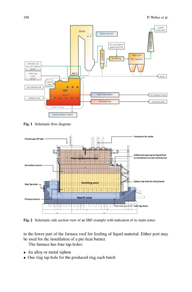
Fig. 1 Schematic flow diagram
Hearth zone
Smelting zone
Post-combustion zone
Process gas off-take
Feed ports for solids
Siphon Tap-Hole for alloy/metal
Slag Tap-Hole
Additional opening for liquid feed
or installment of a pre-heat burner
Secondary tuyeres
Primary tuyeres
Safe Tap-Holes
Fig. 2 Schematic side section view of an SBF example with indication of its main zones
in the lower part of the furnace roof for feeding of liquid material. Either port may
be used for the installation of a pre-heat burner.
The furnace has four tap-holes:
• An alloy or metal siphon
• One slag tap hole for the produced slag each batch
P. Weber et al.
Fig. 1 Schematic flow diagram
Hearth zone
Smelting zone
Post-combustion zone
Process gas off-take
Feed ports for solids
Siphon Tap-Hole for alloy/metal
Slag Tap-Hole
Additional opening for liquid feed
or installment of a pre-heat burner
Secondary tuyeres
Primary tuyeres
Safe Tap-Holes
Fig. 2 Schematic side section view of an SBF example with indication of its main zones
in the lower part of the furnace roof for feeding of liquid material. Either port may
be used for the installation of a pre-heat burner.
The furnace has four tap-holes:
• An alloy or metal siphon
• One slag tap hole for the produced slag each batch