

302
Network-on-Chip
PSO (DPSO) formulation has been developed in Soumya et al. (2013) for mapping the cores onto the NoC architecture and then reconfiguring them with
the application considered.
10.3.7.1 Particle Formulation and Fitness Function
10.3.7.1.1 For Mapping Problem
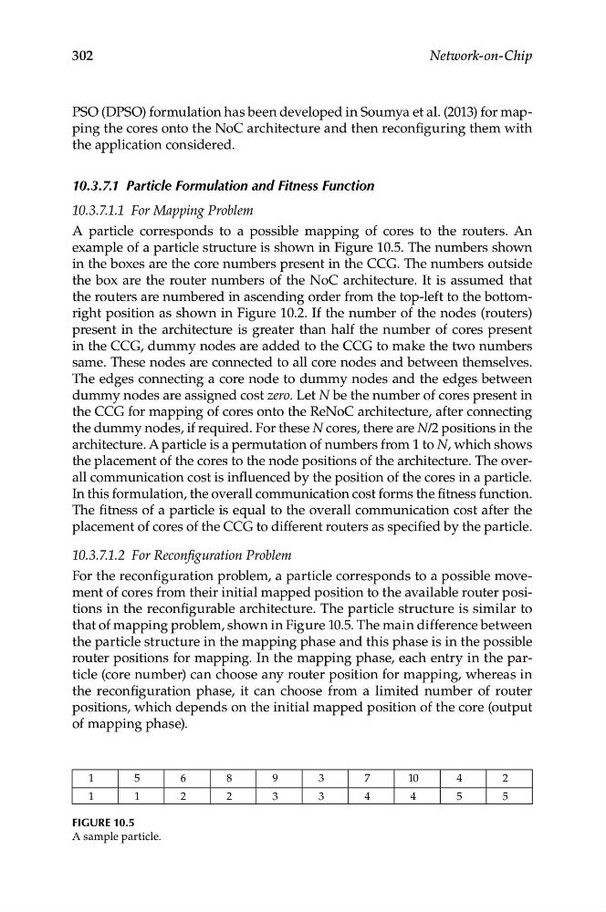
A particle corresponds to a possible mapping of cores to the routers. An
example of a particle structure is shown in Figure 10.5. The numbers shown
in the boxes are the core numbers present in the CCG. The numbers outside
the box are the router numbers of the NoC architecture. It is assumed that
the routers are numbered in ascending order from the top-left to the bottomright position as shown in Figure 10.2. If the number of the nodes (routers)
present in the architecture is greater than half the number of cores present
in the CCG, dummy nodes are added to the CCG to make the two numbers
same. These nodes are connected to all core nodes and between themselves.
The edges connecting a core node to dummy nodes and the edges between
dummy nodes are assigned cost zero. Let N be the number of cores present in
the CCG for mapping of cores onto the ReNoC architecture, after connecting
the dummy nodes, if required. For these N cores, there are N/2 positions in the
architecture. A particle is a permutation of numbers from 1 to N, which shows
the placement of the cores to the node positions of the architecture. The overall communication cost is influenced by the position of the cores in a particle.
In this formulation, the overall communication cost forms the fitness function.
The fitness of a particle is equal to the overall communication cost after the
placement of cores of the CCG to different routers as specified by the particle.
10.3.7.1.2 For Reconfiguration Problem
For the reconfiguration problem, a particle corresponds to a possible movement of cores from their initial mapped position to the available router positions in the reconfigurable architecture. The particle structure is similar to
that of mapping problem, shown in Figure 10.5. The main difference between
the particle structure in the mapping phase and this phase is in the possible
router positions for mapping. In the mapping phase, each entry in the particle (core number) can choose any router position for mapping, whereas in
the reconfiguration phase, it can choose from a limited number of router
positions, which depends on the initial mapped position of the core (output
of mapping phase).
1
5
6
8
9
3
7
10
4
2
1
1
2
2
3
3
4
4
5
5
Figure 10.5
A sample particle.