

272
Network-on-Chip
6
4
2
1
6
6
4
3
10
12
11
2
1
0
9
7
8
5
13
4
3
10
12
11
7
8
2
1
0
9
5
13
0
9
7
8
3
10
12
11
5
13
(a)
(b)
(c)
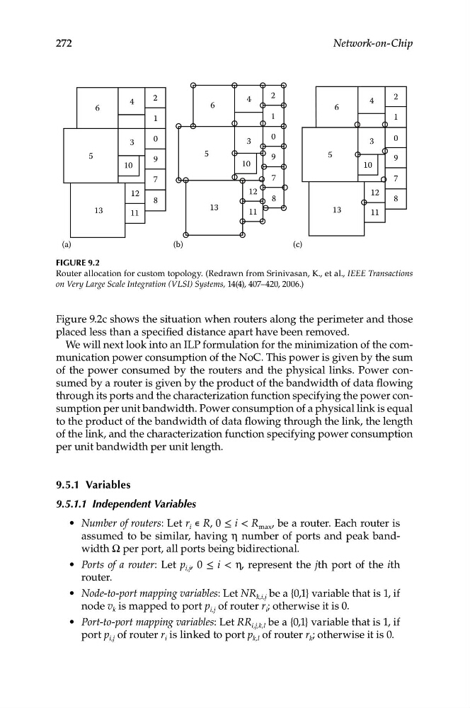
Figure 9.2
Router allocation for custom topology. (Redrawn from Srinivasan, K., et al., IEEE Transactions
on Very Large Scale Integration (VLSI) Systems, 14(4), 407–420, 2006.)
Figure 9.2c shows the situation when routers along the perimeter and those
placed less than a specified distance apart have been removed.
We will next look into an ILP formulation for the minimization of the communication power consumption of the NoC. This power is given by the sum
of the power consumed by the routers and the physical links. Power consumed by a router is given by the product of the bandwidth of data flowing
through its ports and the characterization function specifying the power consumption per unit bandwidth. Power consumption of a physical link is equal
to the product of the bandwidth of data flowing through the link, the length
of the link, and the characterization function specifying power consumption
per unit bandwidth per unit length.
9.5.1 Variables
9.5.1.1 Independent Variables
• Number of routers: Let r i ∊ R, 0 ≤ i < R max , be a router. Each router is
assumed to be similar, having η number of ports and peak bandwidth Ω per port, all ports being bidirectional.
• Ports of a router: Let p i,j , 0 ≤ i < η, represent the jth port of the ith
router.
• Node-to-port mapping variables: Let NR k,i,j be a {0,1} variable that is 1, if
node v k is mapped to port p i,j of router r i ; otherwise it is 0.
• Port-to-port mapping variables: Let RR i,j,k,l be a {0,1} variable that is 1, if
port p i,j of router r i is linked to port p k,l of router r k ; otherwise it is 0.
Network-on-Chip
6
4
2
1
6
6
4
3
10
12
11
2
1
0
9
7
8
5
13
4
3
10
12
11
7
8
2
1
0
9
5
13
0
9
7
8
3
10
12
11
5
13
(a)
(b)
(c)
Figure 9.2
Router allocation for custom topology. (Redrawn from Srinivasan, K., et al., IEEE Transactions
on Very Large Scale Integration (VLSI) Systems, 14(4), 407–420, 2006.)
Figure 9.2c shows the situation when routers along the perimeter and those
placed less than a specified distance apart have been removed.
We will next look into an ILP formulation for the minimization of the communication power consumption of the NoC. This power is given by the sum
of the power consumed by the routers and the physical links. Power consumed by a router is given by the product of the bandwidth of data flowing
through its ports and the characterization function specifying the power consumption per unit bandwidth. Power consumption of a physical link is equal
to the product of the bandwidth of data flowing through the link, the length
of the link, and the characterization function specifying power consumption
per unit bandwidth per unit length.
9.5.1 Variables
9.5.1.1 Independent Variables
• Number of routers: Let r i ∊ R, 0 ≤ i < R max , be a router. Each router is
assumed to be similar, having η number of ports and peak bandwidth Ω per port, all ports being bidirectional.
• Ports of a router: Let p i,j , 0 ≤ i < η, represent the jth port of the ith
router.
• Node-to-port mapping variables: Let NR k,i,j be a {0,1} variable that is 1, if
node v k is mapped to port p i,j of router r i ; otherwise it is 0.
• Port-to-port mapping variables: Let RR i,j,k,l be a {0,1} variable that is 1, if
port p i,j of router r i is linked to port p k,l of router r k ; otherwise it is 0.