

350
A. Agrawal et al.
to simulate transverse failure in realistic virtual models of the composite laminate
and extract the sensitivity of the transverse failure response on the material and
geometrical parameters that define the microstructure of the transverse ply [3–5].
While the IGFEM scheme allows for the detailed simulation of transverse failure
in virtual models composed of hundreds of fibers, larger models of the composite
laminate are needed to further explore statistical effects on the transverse failure
response. To that effect, we develop in this manuscript a geometric model that
combines large reconstructed models of the transverse ply taken from optical images
with a simplified model of transverse crack initiation and a shear lag model of crack
shielding. This work builds on the theoretical studies of Garret and Bailey [6] and
Parvizi and Bailey [7], who used a homogenized model of the transverse ply in
their prediction of the relation between applied transverse loading of the laminate
and the evolution of transverse cracking in the 90 ◦ ply. In contrast, the present
study incorporates details of the transverse ply microstructure extracted from optical
images of the composite laminates used in the experiments [2].
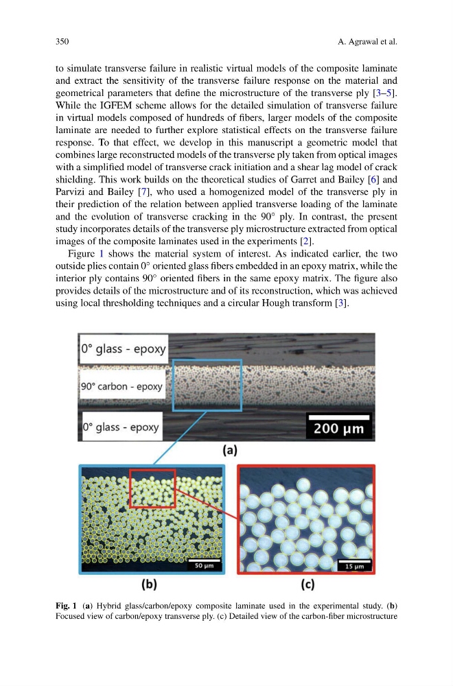
Figure 1 shows the material system of interest. As indicated earlier, the two
outside plies contain 0 ◦ oriented glass fibers embedded in an epoxy matrix, while the
interior ply contains 90 ◦ oriented fibers in the same epoxy matrix. The figure also
provides details of the microstructure and of its reconstruction, which was achieved
using local thresholding techniques and a circular Hough transform [3].
Fig. 1 (a) Hybrid glass/carbon/epoxy composite laminate used in the experimental study. (b)
Focused view of carbon/epoxy transverse ply. (c) Detailed view of the carbon-fiber microstructure
A. Agrawal et al.
to simulate transverse failure in realistic virtual models of the composite laminate
and extract the sensitivity of the transverse failure response on the material and
geometrical parameters that define the microstructure of the transverse ply [3–5].
While the IGFEM scheme allows for the detailed simulation of transverse failure
in virtual models composed of hundreds of fibers, larger models of the composite
laminate are needed to further explore statistical effects on the transverse failure
response. To that effect, we develop in this manuscript a geometric model that
combines large reconstructed models of the transverse ply taken from optical images
with a simplified model of transverse crack initiation and a shear lag model of crack
shielding. This work builds on the theoretical studies of Garret and Bailey [6] and
Parvizi and Bailey [7], who used a homogenized model of the transverse ply in
their prediction of the relation between applied transverse loading of the laminate
and the evolution of transverse cracking in the 90 ◦ ply. In contrast, the present
study incorporates details of the transverse ply microstructure extracted from optical
images of the composite laminates used in the experiments [2].
Figure 1 shows the material system of interest. As indicated earlier, the two
outside plies contain 0 ◦ oriented glass fibers embedded in an epoxy matrix, while the
interior ply contains 90 ◦ oriented fibers in the same epoxy matrix. The figure also
provides details of the microstructure and of its reconstruction, which was achieved
using local thresholding techniques and a circular Hough transform [3].
Fig. 1 (a) Hybrid glass/carbon/epoxy composite laminate used in the experimental study. (b)
Focused view of carbon/epoxy transverse ply. (c) Detailed view of the carbon-fiber microstructure