

174
J. Hochhalter et al.
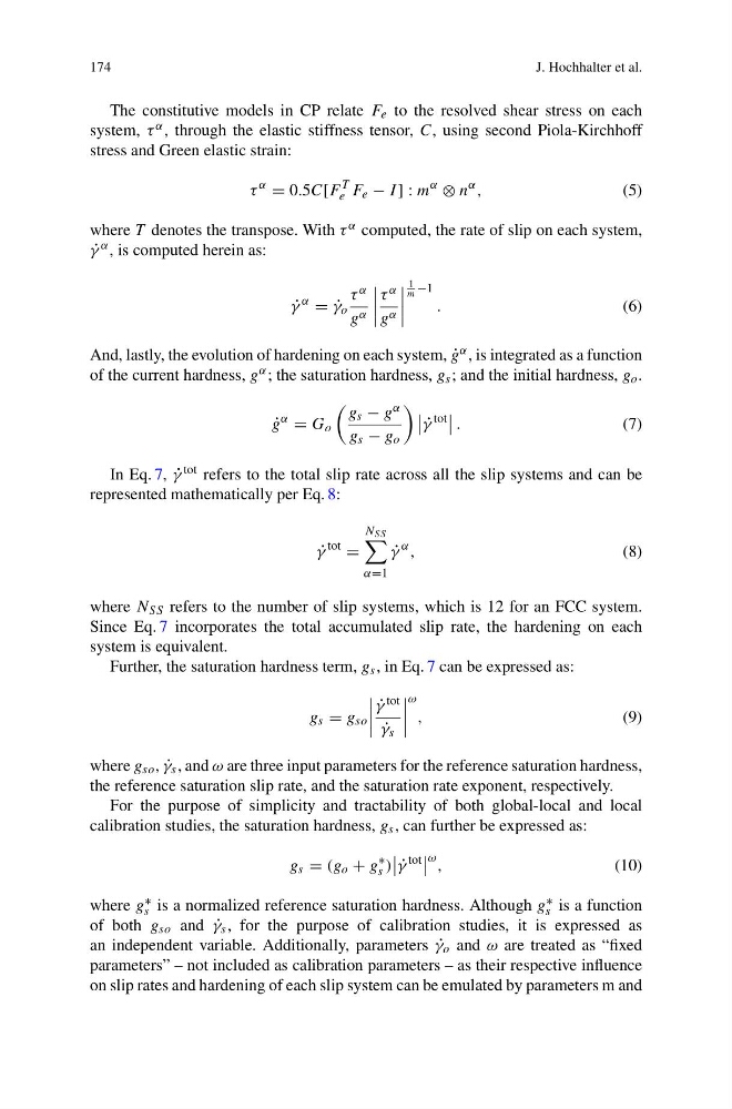
The constitutive models in CP relate F e to the resolved shear stress on each
system, τ α , through the elastic stiffness tensor, C, using second Piola-Kirchhoff
stress and Green elastic strain:
τ
α
= 0.5C[F
T
e F e − I ] : m
α
⊗ n
α ,
(5)
where T denotes the transpose. With τ α computed, the rate of slip on each system,
˙
γ α , is computed herein as:
˙
γ
α
= ˙
γ o
τ α
g α
τ α
g α
1
m −1
.
(6)
And, lastly, the evolution of hardening on each system, ˙
g α , is integrated as a function
of the current hardness, g α ; the saturation hardness, g s ; and the initial hardness, g o .
˙
g
α
= G o
g s − g α
g s − g o
˙
γ
tot
.
(7)
In Eq. 7, ˙
γ tot refers to the total slip rate across all the slip systems and can be
represented mathematically per Eq. 8:
˙
γ
tot
=
N SS
α=1
˙
γ
α ,
(8)
where N SS refers to the number of slip systems, which is 12 for an FCC system.
Since Eq. 7 incorporates the total accumulated slip rate, the hardening on each
system is equivalent.
Further, the saturation hardness term, g s , in Eq. 7 can be expressed as:
g s = g so
˙
γ tot
˙
γ s
ω
,
(9)
where g so , ˙
γ s , and ω are three input parameters for the reference saturation hardness,
the reference saturation slip rate, and the saturation rate exponent, respectively.
For the purpose of simplicity and tractability of both global-local and local
calibration studies, the saturation hardness, g s , can further be expressed as:
g s = (g o + g
∗
s )
˙
γ
tot
ω ,
(10)
where g ∗
s is a normalized reference saturation hardness. Although g ∗
s is a function
of both g so and ˙
γ s , for the purpose of calibration studies, it is expressed as
an independent variable. Additionally, parameters ˙
γ o and ω are treated as “fixed
parameters” – not included as calibration parameters – as their respective influence
on slip rates and hardening of each slip system can be emulated by parameters m and
J. Hochhalter et al.
The constitutive models in CP relate F e to the resolved shear stress on each
system, τ α , through the elastic stiffness tensor, C, using second Piola-Kirchhoff
stress and Green elastic strain:
τ
α
= 0.5C[F
T
e F e − I ] : m
α
⊗ n
α ,
(5)
where T denotes the transpose. With τ α computed, the rate of slip on each system,
˙
γ α , is computed herein as:
˙
γ
α
= ˙
γ o
τ α
g α
τ α
g α
1
m −1
.
(6)
And, lastly, the evolution of hardening on each system, ˙
g α , is integrated as a function
of the current hardness, g α ; the saturation hardness, g s ; and the initial hardness, g o .
˙
g
α
= G o
g s − g α
g s − g o
˙
γ
tot
.
(7)
In Eq. 7, ˙
γ tot refers to the total slip rate across all the slip systems and can be
represented mathematically per Eq. 8:
˙
γ
tot
=
N SS
α=1
˙
γ
α ,
(8)
where N SS refers to the number of slip systems, which is 12 for an FCC system.
Since Eq. 7 incorporates the total accumulated slip rate, the hardening on each
system is equivalent.
Further, the saturation hardness term, g s , in Eq. 7 can be expressed as:
g s = g so
˙
γ tot
˙
γ s
ω
,
(9)
where g so , ˙
γ s , and ω are three input parameters for the reference saturation hardness,
the reference saturation slip rate, and the saturation rate exponent, respectively.
For the purpose of simplicity and tractability of both global-local and local
calibration studies, the saturation hardness, g s , can further be expressed as:
g s = (g o + g
∗
s )
˙
γ
tot
ω ,
(10)
where g ∗
s is a normalized reference saturation hardness. Although g ∗
s is a function
of both g so and ˙
γ s , for the purpose of calibration studies, it is expressed as
an independent variable. Additionally, parameters ˙
γ o and ω are treated as “fixed
parameters” – not included as calibration parameters – as their respective influence
on slip rates and hardening of each slip system can be emulated by parameters m and