

140
A. Cruzado et al.
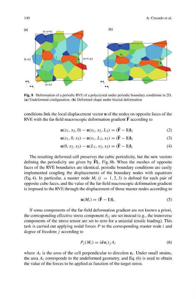
Fig. 8 Deformation of a periodic RVE of a polycrystal under periodic boundary conditions in 2D.
(a) Undeformed configuration. (b) Deformed shape under biaxial deformation
conditions link the local displacement vector u of the nodes on opposite faces of the
RVE with the far-field macroscopic deformation gradient ¯
F according to
u(x 1 , x 2 , 0) − u(x 1 , x 2 , L 3 ) = ( ¯
F − 1)l 3
(2)
u(x 1 , 0, x 3 ) − u(x 1 , L 2 , x 3 ) = ( ¯
F − 1)l 2
(3)
u(0, x 2 , x 3 ) − u(L 1 , x 2 , x 3 ) = ( ¯
F − 1)l 1
(4)
The resulting deformed cell preserves the cubic periodicity, but the new vectors
defining the periodicity are given by ¯
Fl i , Fig. 8b. When the meshes of opposite
faces of the RVE boundaries are identical, periodic boundary conditions are easily
implemented coupling the displacements of the boundary nodes with equations
(Eq. 4). In particular, a master node M i (i = 1, 2, 3) is defined for each pair of
opposite cube faces, and the value of the far-field macroscopic deformation gradient
is imposed to the RVE through the displacement of those master nodes according to
u(M i ) = ( ¯
F − 1)l i .
(5)
If some components of the far-field deformation gradient are not known a priori,
the corresponding effective stress component ¯
σ ij are set instead (e.g., the transverse
components of the stress tensor are set to zero for a uniaxial tensile loading). This
task is carried out applying nodal forces P to the corresponding master node i and
degree of freedom j according to
P j (M i ) = ( ¯
σ e i ) j A i
(6)
where A i is the area of the cell perpendicular to direction e i . Under small strains,
the area A i corresponds to the undeformed geometry, and Eq. (6) is used to obtain
the value of the forces to be applied as function of the target stress.
A. Cruzado et al.
Fig. 8 Deformation of a periodic RVE of a polycrystal under periodic boundary conditions in 2D.
(a) Undeformed configuration. (b) Deformed shape under biaxial deformation
conditions link the local displacement vector u of the nodes on opposite faces of the
RVE with the far-field macroscopic deformation gradient ¯
F according to
u(x 1 , x 2 , 0) − u(x 1 , x 2 , L 3 ) = ( ¯
F − 1)l 3
(2)
u(x 1 , 0, x 3 ) − u(x 1 , L 2 , x 3 ) = ( ¯
F − 1)l 2
(3)
u(0, x 2 , x 3 ) − u(L 1 , x 2 , x 3 ) = ( ¯
F − 1)l 1
(4)
The resulting deformed cell preserves the cubic periodicity, but the new vectors
defining the periodicity are given by ¯
Fl i , Fig. 8b. When the meshes of opposite
faces of the RVE boundaries are identical, periodic boundary conditions are easily
implemented coupling the displacements of the boundary nodes with equations
(Eq. 4). In particular, a master node M i (i = 1, 2, 3) is defined for each pair of
opposite cube faces, and the value of the far-field macroscopic deformation gradient
is imposed to the RVE through the displacement of those master nodes according to
u(M i ) = ( ¯
F − 1)l i .
(5)
If some components of the far-field deformation gradient are not known a priori,
the corresponding effective stress component ¯
σ ij are set instead (e.g., the transverse
components of the stress tensor are set to zero for a uniaxial tensile loading). This
task is carried out applying nodal forces P to the corresponding master node i and
degree of freedom j according to
P j (M i ) = ( ¯
σ e i ) j A i
(6)
where A i is the area of the cell perpendicular to direction e i . Under small strains,
the area A i corresponds to the undeformed geometry, and Eq. (6) is used to obtain
the value of the forces to be applied as function of the target stress.