

Microscale Testing and Characterization Techniques for Benchmarking Crystal. . .
111
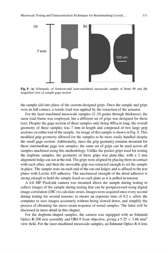
Fig. 8 (a) Schematic of femtosecond laser-machined mesoscale sample of René 88 and (b)
magnified view of sample gage section
the sample slid into place of the custom-designed grips. Once the sample and grips
were in full contact, a tensile load was applied by the retraction of the actuator.
For the laser-machined mesoscale samples (2–10 grains through thickness), the
same load frame was employed, but a different set of grips was designed for these
tests. Despite the gage section of these samples only being 400 μm long, the overall
geometry of these samples was 7 mm in length and composed of two large grip
sections on either end of the sample. An image of this sample is shown in Fig. 8. This
modified grip geometry allowed for the samples to be more easily handled despite
the small gage section. Additionally, since the grip geometry remains invariant for
these intermediate gage size samples, the same set of grips can be used across all
samples machined using this methodology. Unlike the pocket grips used for testing
the dogbone samples, the geometry of these grips was plate-like, with a 2 mm
alignment ledge cut out at the end. The grips were aligned by placing them in contact
with each other, and then the moveable grip was retracted enough to set the sample
in place. The sample rests on each end of the cut-out ledges and is affixed to the test
plates with Loctite 420 adhesive. The mechanical strength of the dried adhesive is
strong enough to hold the sample fixed on each plate as it is pulled in tension.
A 6.6 MP PixeLink camera was mounted above the sample during testing to
collect images of the sample during testing that can be postprocessed using digital
image correlation (DIC) to calculate strain. Images were acquired once every second
during testing for several reasons: to ensure an exposure time of 0.2 s, allow the
computer to save images accurately without being slowed down, and simplify the
process of obtaining the stress-strain response of tested samples. The latter will be
discussed in more detail in this chapter.
For the dogbone-shaped samples, the camera was equipped with an Edmund
Optics R-200 rear assembly and OBJ-9 front objective, giving a 5.25 × 3.86 mm 2
view field. For the laser-machined mesoscale samples, an Edmund Optics R-6 lens
111
Fig. 8 (a) Schematic of femtosecond laser-machined mesoscale sample of René 88 and (b)
magnified view of sample gage section
the sample slid into place of the custom-designed grips. Once the sample and grips
were in full contact, a tensile load was applied by the retraction of the actuator.
For the laser-machined mesoscale samples (2–10 grains through thickness), the
same load frame was employed, but a different set of grips was designed for these
tests. Despite the gage section of these samples only being 400 μm long, the overall
geometry of these samples was 7 mm in length and composed of two large grip
sections on either end of the sample. An image of this sample is shown in Fig. 8. This
modified grip geometry allowed for the samples to be more easily handled despite
the small gage section. Additionally, since the grip geometry remains invariant for
these intermediate gage size samples, the same set of grips can be used across all
samples machined using this methodology. Unlike the pocket grips used for testing
the dogbone samples, the geometry of these grips was plate-like, with a 2 mm
alignment ledge cut out at the end. The grips were aligned by placing them in contact
with each other, and then the moveable grip was retracted enough to set the sample
in place. The sample rests on each end of the cut-out ledges and is affixed to the test
plates with Loctite 420 adhesive. The mechanical strength of the dried adhesive is
strong enough to hold the sample fixed on each plate as it is pulled in tension.
A 6.6 MP PixeLink camera was mounted above the sample during testing to
collect images of the sample during testing that can be postprocessed using digital
image correlation (DIC) to calculate strain. Images were acquired once every second
during testing for several reasons: to ensure an exposure time of 0.2 s, allow the
computer to save images accurately without being slowed down, and simplify the
process of obtaining the stress-strain response of tested samples. The latter will be
discussed in more detail in this chapter.
For the dogbone-shaped samples, the camera was equipped with an Edmund
Optics R-200 rear assembly and OBJ-9 front objective, giving a 5.25 × 3.86 mm 2
view field. For the laser-machined mesoscale samples, an Edmund Optics R-6 lens