

63
Review of Basic Device Physics
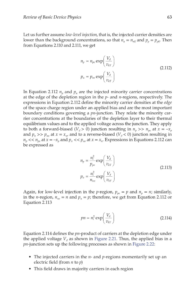
Let us further assume low-level injection, that is, the injected carrier densities are
lower than the background concentrations, so that n n = n n0 and p p = p p0 . Then
from Equations 2.110 and 2.111, we get
n
n
V
v
p
p
V
v
p
p o
d
kT
n
n o
d
kT
=
=
exp
exp
(2.112)
In Equation 2.112 n p and p n are the injected minority carrier concentrations
at the edge of the depletion region in the p- and n-regions, respectively. The
expressions in Equation 2.112 define the minority carrier densities at the edge
of the space charge region under an applied bias and are the most important
boundary conditions governing a pn-junction. They relate the minority carrier concentrations at the boundaries of the depletion layer to their thermal
equilibrium values and to the applied voltage across the junction. They apply
to both a forward-biased (V d > 0) junction resulting in n p >> n po at x = –x p
and p n >> p no at x = x n , and to a reverse-biased (V d < 0) junction resulting in
n p << n po at x = –x p and p n << p no at x = x n . Expressions in Equations 2.112 can
be expressed as
n
n
p
V
v
p
n
n
V
v
p
i
po
d
kT
n
i
n
d
kT
=
=
2
2
exp
exp
o
(2.113)
Again, for low-level injection in the p-region, p po = p and n p = n; similarly,
in the n-region, n no = n and p n = p; therefore, we get from Equation 2.112 or
Equation 2.113
pn n
V
v
i
d
kT
=
2 exp
(2.114)
Equation 2.114 defines the pn-product of carriers at the depletion edge under
the applied voltage V d as shown in Figure 2.21. Thus, the applied bias in a
pn-junction sets up the following processes as shown in Figure 2.22:
• The injected carriers in the n- and p-regions momentarily set up an
electric field (from n to p)
• This field draws in majority carriers in each region
Review of Basic Device Physics
Let us further assume low-level injection, that is, the injected carrier densities are
lower than the background concentrations, so that n n = n n0 and p p = p p0 . Then
from Equations 2.110 and 2.111, we get
n
n
V
v
p
p
V
v
p
p o
d
kT
n
n o
d
kT
=
=
exp
exp
(2.112)
In Equation 2.112 n p and p n are the injected minority carrier concentrations
at the edge of the depletion region in the p- and n-regions, respectively. The
expressions in Equation 2.112 define the minority carrier densities at the edge
of the space charge region under an applied bias and are the most important
boundary conditions governing a pn-junction. They relate the minority carrier concentrations at the boundaries of the depletion layer to their thermal
equilibrium values and to the applied voltage across the junction. They apply
to both a forward-biased (V d > 0) junction resulting in n p >> n po at x = –x p
and p n >> p no at x = x n , and to a reverse-biased (V d < 0) junction resulting in
n p << n po at x = –x p and p n << p no at x = x n . Expressions in Equations 2.112 can
be expressed as
n
n
p
V
v
p
n
n
V
v
p
i
po
d
kT
n
i
n
d
kT
=
=
2
2
exp
exp
o
(2.113)
Again, for low-level injection in the p-region, p po = p and n p = n; similarly,
in the n-region, n no = n and p n = p; therefore, we get from Equation 2.112 or
Equation 2.113
pn n
V
v
i
d
kT
=
2 exp
(2.114)
Equation 2.114 defines the pn-product of carriers at the depletion edge under
the applied voltage V d as shown in Figure 2.21. Thus, the applied bias in a
pn-junction sets up the following processes as shown in Figure 2.22:
• The injected carriers in the n- and p-regions momentarily set up an
electric field (from n to p)
• This field draws in majority carriers in each region