

425
Compact Model Library for Circuit Simulation
and devices to extract real-device effects describing physical and geometrical effects. With reference to BSIM4 model, the device selection criteria for
extracting the compact device model parameters of a target CMOS technology
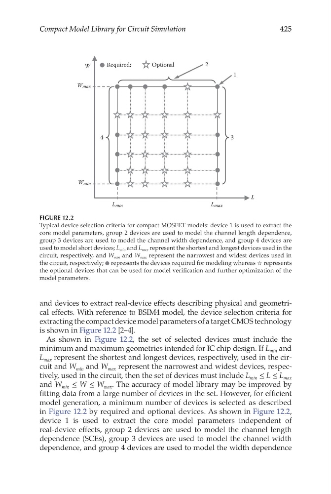
is shown in Figure 12.2 [2–4].
As shown in Figure 12.2, the set of selected devices must include the
minimum and maximum geometries intended for IC chip design. If L min and
L max represent the shortest and longest devices, respectively, used in the circuit and W min and W max represent the narrowest and widest devices, respectively, used in the circuit, then the set of devices must include L min ≤ L ≤ L max
and W min ≤ W ≤ W max . The accuracy of model library may be improved by
fitting data from a large number of devices in the set. However, for efficient
model generation, a minimum number of devices is selected as described
in Figure 12.2 by required and optional devices. As shown in Figure 12.2,
device 1 is used to extract the core model parameters independent of
real-device effects, group 2 devices are used to model the channel length
dependence (SCEs), group 3 devices are used to model the channel width
dependence, and group 4 devices are used to model the width dependence
Required;
O ptional
1
2
3
4
L
W
Wmax
Lmax
Wmin
Lmin
FIGURE 12.2
Typical device selection criteria for compact MOSFET models: device 1 is used to extract the
core model parameters, group 2 devices are used to model the channel length dependence,
group 3 devices are used to model the channel width dependence, and group 4 devices are
used to model short devices; L min and L max represent the shortest and longest devices used in the
circuit, respectively, and W min and W max represent the narrowest and widest devices used in
the circuit, respectively; ⚫ represents the devices required for modeling whereas ☆ represents
the optional devices that can be used for model verification and further optimization of the
model parameters.
Compact Model Library for Circuit Simulation
and devices to extract real-device effects describing physical and geometrical effects. With reference to BSIM4 model, the device selection criteria for
extracting the compact device model parameters of a target CMOS technology
is shown in Figure 12.2 [2–4].
As shown in Figure 12.2, the set of selected devices must include the
minimum and maximum geometries intended for IC chip design. If L min and
L max represent the shortest and longest devices, respectively, used in the circuit and W min and W max represent the narrowest and widest devices, respectively, used in the circuit, then the set of devices must include L min ≤ L ≤ L max
and W min ≤ W ≤ W max . The accuracy of model library may be improved by
fitting data from a large number of devices in the set. However, for efficient
model generation, a minimum number of devices is selected as described
in Figure 12.2 by required and optional devices. As shown in Figure 12.2,
device 1 is used to extract the core model parameters independent of
real-device effects, group 2 devices are used to model the channel length
dependence (SCEs), group 3 devices are used to model the channel width
dependence, and group 4 devices are used to model the width dependence
Required;
O ptional
1
2
3
4
L
W
Wmax
Lmax
Wmin
Lmin
FIGURE 12.2
Typical device selection criteria for compact MOSFET models: device 1 is used to extract the
core model parameters, group 2 devices are used to model the channel length dependence,
group 3 devices are used to model the channel width dependence, and group 4 devices are
used to model short devices; L min and L max represent the shortest and longest devices used in the
circuit, respectively, and W min and W max represent the narrowest and widest devices used in
the circuit, respectively; ⚫ represents the devices required for modeling whereas ☆ represents
the optional devices that can be used for model verification and further optimization of the
model parameters.