

276
Compact Models for Integrated Circuit Design
where:
Q i is the amount of channel inversion charge per unit area
E LM is a parameter, referred to as the Elmore constant (=5) that is used to
match the lowest frequency pole
It is reported that the value of E LM required to match the output of different
possible equivalent circuits is about 3 and it is invariant with respect to
W and L [35]. The comparison of the time and frequency domain responses
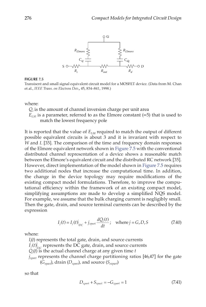
of the Elmore equivalent network shown in Figure 7.5 with the conventional
distributed channel representation of a device shows a reasonable match
between the Elmore’s equivalent circuit and the distributed RC network [35].
However, direct implementation of the model shown in Figure 7.5 requires
two additional nodes that increase the computational time. In addition,
the change in the device topology may require modifications of the
existing compact model formulations. Therefore, to improve the computational efficiency within the framework of an existing compact model,
simplifying assumptions are made to develop a simplified NQS model.
For example, we assume that the bulk charging current is negligibly small.
Then the gate, drain, and source terminal currents can be described by the
expression
I t I t
j
dQ t
dt
j G D S
j
j
DC
xpart
i
( )
( )
( ) ;
, ,
=
+
=
where
(7.40)
where:
I j (t) represents the total gate, drain, and source currents
I t
j
DC
( ) represents the DC gate, drain, and source currents
Q i (t) is the actual channel charge at any given time t
j xpart represents the channel charge partitioning ratios [46,47] for the gate
(G xpart ), drain (D xpart ), and source (S expart )
so that
D
S
G
xpart
xpart
xpart
+
=
=
–
1
(7.41)
G
R Elmore
R Elmore
C dg
C sg
R s
R out
R d
D
S
FIGURE 7.5
Transisent and small signal equivalent circuit model for a MOSFET device. (Data from M. Chan
et al., IEEE Trans. on Electron Dev., 45, 834–841, 1998.)
Compact Models for Integrated Circuit Design
where:
Q i is the amount of channel inversion charge per unit area
E LM is a parameter, referred to as the Elmore constant (=5) that is used to
match the lowest frequency pole
It is reported that the value of E LM required to match the output of different
possible equivalent circuits is about 3 and it is invariant with respect to
W and L [35]. The comparison of the time and frequency domain responses
of the Elmore equivalent network shown in Figure 7.5 with the conventional
distributed channel representation of a device shows a reasonable match
between the Elmore’s equivalent circuit and the distributed RC network [35].
However, direct implementation of the model shown in Figure 7.5 requires
two additional nodes that increase the computational time. In addition,
the change in the device topology may require modifications of the
existing compact model formulations. Therefore, to improve the computational efficiency within the framework of an existing compact model,
simplifying assumptions are made to develop a simplified NQS model.
For example, we assume that the bulk charging current is negligibly small.
Then the gate, drain, and source terminal currents can be described by the
expression
I t I t
j
dQ t
dt
j G D S
j
j
DC
xpart
i
( )
( )
( ) ;
, ,
=
+
=
where
(7.40)
where:
I j (t) represents the total gate, drain, and source currents
I t
j
DC
( ) represents the DC gate, drain, and source currents
Q i (t) is the actual channel charge at any given time t
j xpart represents the channel charge partitioning ratios [46,47] for the gate
(G xpart ), drain (D xpart ), and source (S expart )
so that
D
S
G
xpart
xpart
xpart
+
=
=
–
1
(7.41)
G
R Elmore
R Elmore
C dg
C sg
R s
R out
R d
D
S
FIGURE 7.5
Transisent and small signal equivalent circuit model for a MOSFET device. (Data from M. Chan
et al., IEEE Trans. on Electron Dev., 45, 834–841, 1998.)