

Chapter 3: The Theory of Automata &;! 73
I
i
1
1
q1' q2' '
~
I Q15' Q16'
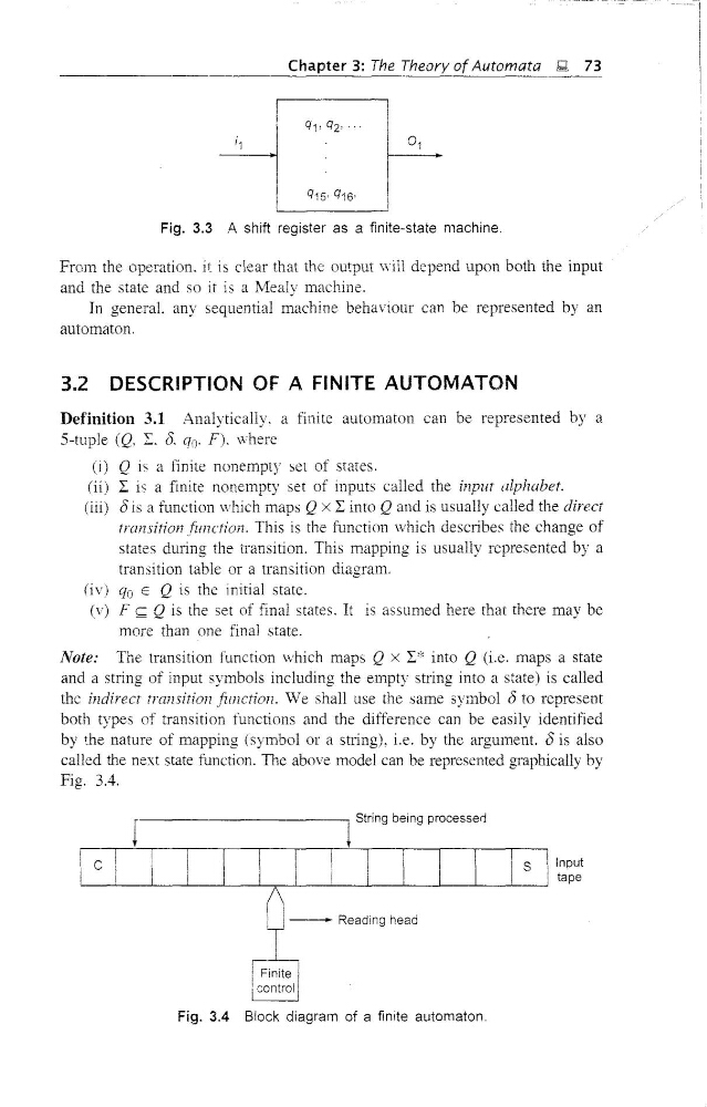
Fig. 3.3 .A shift register as a finite-state machine,
From the operation. it is clear that the output will depend upon both the input
and the state and so it is a Mealy machine.
In general. any sequential machine behaviour can be represented by an
automaton.
3.2 DESCRIPTION OF A FINITE AUTOMATON
Definition 3.1 Analytically. a finite automaton can be represented by a
5-tuple (Q, E. 0. qo. F). where
(i) Q is a finite nonempty set of states.
(ii) I is a finite nonempty set of inputs called the input alphabet.
(iii) (5 is a function which maps Q x I into Q and is usually called the direct
transition function. This is the function which describes the change of
states during the transition. This mapping is usually represented by a
transition table or a transition diagram.
(iv) qo E Q is the initial state.
(v) F <;:;;; Q is the set of final states. It is assumed here that there may be
more than one final state.
Note: The transition function \vhich maps Q x I* into Q (i.e. maps a state
and a string of input symbols including the empty stling into a state) is called
the indirect transition function. We shall use the same symbol (5 to represent
both types of transition functions and the difference can be easily identified
by the nature of mapping (symbol or a string), i.e. by the argument. (5 is also
called the next state function. The above model can be represented graphically by
Fig. 3.4.
D
c
r-------------,t String being processerJ
I I I [ I I I S Ilt~~~t
n
- -
1-" "dieg h,,,
i Finite
! control
Fig. 3.4 Block diagram of a finite automaton.
I
i
1
1
q1' q2' '
~
I Q15' Q16'
Fig. 3.3 .A shift register as a finite-state machine,
From the operation. it is clear that the output will depend upon both the input
and the state and so it is a Mealy machine.
In general. any sequential machine behaviour can be represented by an
automaton.
3.2 DESCRIPTION OF A FINITE AUTOMATON
Definition 3.1 Analytically. a finite automaton can be represented by a
5-tuple (Q, E. 0. qo. F). where
(i) Q is a finite nonempty set of states.
(ii) I is a finite nonempty set of inputs called the input alphabet.
(iii) (5 is a function which maps Q x I into Q and is usually called the direct
transition function. This is the function which describes the change of
states during the transition. This mapping is usually represented by a
transition table or a transition diagram.
(iv) qo E Q is the initial state.
(v) F <;:;;; Q is the set of final states. It is assumed here that there may be
more than one final state.
Note: The transition function \vhich maps Q x I* into Q (i.e. maps a state
and a string of input symbols including the empty stling into a state) is called
the indirect transition function. We shall use the same symbol (5 to represent
both types of transition functions and the difference can be easily identified
by the nature of mapping (symbol or a string), i.e. by the argument. (5 is also
called the next state function. The above model can be represented graphically by
Fig. 3.4.
D
c
r-------------,t String being processerJ
I I I [ I I I S Ilt~~~t
n
- -
1-" "dieg h,,,
i Finite
! control
Fig. 3.4 Block diagram of a finite automaton.