

Chapter 9: Turing Machines and Linear Bounded Automata Q 281
we get exf3y in the table, it means that ex is written in the current cell, f3 gives
the movement of the head (L or R) and y denotes the new state into which the
Turing machine enters.
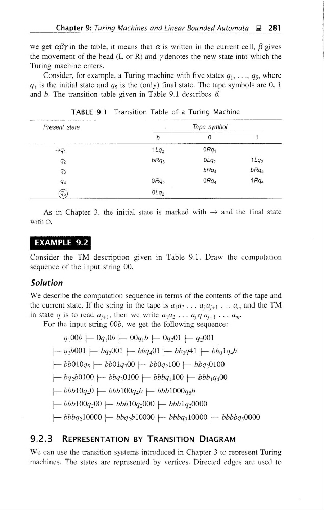
Consider, for example, a Turing machine with five states qj, ..., qs, where
ql is the initial state and qs is the (only) final state. The tape symbols are 0. 1
and b. The transition table given in Table 9.1 describes 8.
TABLE 9.1 Transition Table of a Turing Machine
Present state
Tape symbol
b
0
-'7q1
1Lq2
ORq1
q2
bRq3
OLq2
1Lq2
q3
bRq4
bRq5
q4
ORq5
ORQ4
1RQ4
®
OLQ2
As in Chapter 3. the initial state is marked with ~ and the final state
witho.
EXAMPLE 9.2
Consider the TM description given m Table 9.1. Draw the computation
sequence of the input string 00.
Solution
We describe the computation sequence in terms of the contents of the tape and
the current state. If the string in the tape is al(l2
G;(l;+l ... alii and the TM
in state q is to read aj+ 1, then we write a 1a2
G; q (l;+ 1 ••• all/'
For the input string OOb, we get the following sequence:
qt OOb r- Oqt Ob r- OOq,b r- Oq2 01 r- q2 001
r- q2 bOOl r- bq3 001 r- bbq401 r- bb o q41 r- bb o 1q4b
r- bbOlOqs r- bb01q200 r- bbOq2 100 r- bbq20100
r- bq2 bOlOO r- bbq3 0100 r- bbbq4 100 r- bbb j q400
r- bbblOq40 r- bbblOOq4b r- bbblOOOqsb
r- bbb 100q200 r- bbb lOq2000 r- bbb 1q20000
r-bbbq210000 r- bbq2b10000 r- bbbq310000 r- bbbbqsOOOO
9.2.3 REPRESENTATION BY TRANSITION DIAGRAM
We can use the transition systems introduced in Chapter 3 to represent Turing
machines. The states are represented by veltices. Directed edges are used to
we get exf3y in the table, it means that ex is written in the current cell, f3 gives
the movement of the head (L or R) and y denotes the new state into which the
Turing machine enters.
Consider, for example, a Turing machine with five states qj, ..., qs, where
ql is the initial state and qs is the (only) final state. The tape symbols are 0. 1
and b. The transition table given in Table 9.1 describes 8.
TABLE 9.1 Transition Table of a Turing Machine
Present state
Tape symbol
b
0
-'7q1
1Lq2
ORq1
q2
bRq3
OLq2
1Lq2
q3
bRq4
bRq5
q4
ORq5
ORQ4
1RQ4
®
OLQ2
As in Chapter 3. the initial state is marked with ~ and the final state
witho.
EXAMPLE 9.2
Consider the TM description given m Table 9.1. Draw the computation
sequence of the input string 00.
Solution
We describe the computation sequence in terms of the contents of the tape and
the current state. If the string in the tape is al(l2
G;(l;+l ... alii and the TM
in state q is to read aj+ 1, then we write a 1a2
G; q (l;+ 1 ••• all/'
For the input string OOb, we get the following sequence:
qt OOb r- Oqt Ob r- OOq,b r- Oq2 01 r- q2 001
r- q2 bOOl r- bq3 001 r- bbq401 r- bb o q41 r- bb o 1q4b
r- bbOlOqs r- bb01q200 r- bbOq2 100 r- bbq20100
r- bq2 bOlOO r- bbq3 0100 r- bbbq4 100 r- bbb j q400
r- bbblOq40 r- bbblOOq4b r- bbblOOOqsb
r- bbb 100q200 r- bbb lOq2000 r- bbb 1q20000
r-bbbq210000 r- bbq2b10000 r- bbbq310000 r- bbbbqsOOOO
9.2.3 REPRESENTATION BY TRANSITION DIAGRAM
We can use the transition systems introduced in Chapter 3 to represent Turing
machines. The states are represented by veltices. Directed edges are used to