

40
Digital Electronics
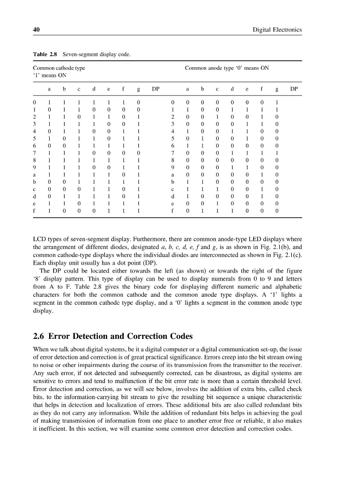
Table 2.8 Seven-segment display code.
Common cathode type
‘1’ means ON
Common anode type ‘0’ means ON
a
b
c
d
e
f
g
DP
a
b
c
d
e
f
g
DP
0
1
1
1
1
1
1
0
0
0
0
0
0
0
0
1
1
0
1
1
0
0
0
0
1
1
0
0
1
1
1
1
2
1
1
0
1
1
0
1
2
0
0
1
0
0
1
0
3
1
1
1
1
0
0
1
3
0
0
0
0
1
1
0
4
0
1
1
0
0
1
1
4
1
0
0
1
1
0
0
5
1
0
1
1
0
1
1
5
0
1
0
0
1
0
0
6
0
0
1
1
1
1
1
6
1
1
0
0
0
0
0
7
1
1
1
0
0
0
0
7
0
0
0
1
1
1
1
8
1
1
1
1
1
1
1
8
0
0
0
0
0
0
0
9
1
1
1
0
0
1
1
9
0
0
0
1
1
0
0
a
1
1
1
1
1
0
1
a
0
0
0
0
0
1
0
b
0
0
1
1
1
1
1
b
1
1
0
0
0
0
0
c
0
0
0
1
1
0
1
c
1
1
1
0
0
1
0
d
0
1
1
1
1
0
1
d
1
0
0
0
0
1
0
e
1
1
0
1
1
1
1
e
0
0
1
0
0
0
0
f
1
0
0
0
1
1
1
f
0
1
1
1
0
0
0
LCD types of seven-segment display. Furthermore, there are common anode-type LED displays where
the arrangement of different diodes, designated a, b, c, d, e, f and g, is as shown in Fig. 2.1(b), and
common cathode-type displays where the individual diodes are interconnected as shown in Fig. 2.1(c).
Each display unit usually has a dot point (DP).
The DP could be located either towards the left (as shown) or towards the right of the figure
‘8’ display pattern. This type of display can be used to display numerals from 0 to 9 and letters
from A to F. Table 2.8 gives the binary code for displaying different numeric and alphabetic
characters for both the common cathode and the common anode type displays. A ‘1’ lights a
segment in the common cathode type display, and a ‘0’ lights a segment in the common anode type
display.
2.6 Error Detection and Correction Codes
When we talk about digital systems, be it a digital computer or a digital communication set-up, the issue
of error detection and correction is of great practical significance. Errors creep into the bit stream owing
to noise or other impairments during the course of its transmission from the transmitter to the receiver.
Any such error, if not detected and subsequently corrected, can be disastrous, as digital systems are
sensitive to errors and tend to malfunction if the bit error rate is more than a certain threshold level.
Error detection and correction, as we will see below, involves the addition of extra bits, called check
bits, to the information-carrying bit stream to give the resulting bit sequence a unique characteristic
that helps in detection and localization of errors. These additional bits are also called redundant bits
as they do not carry any information. While the addition of redundant bits helps in achieving the goal
of making transmission of information from one place to another error free or reliable, it also makes
it inefficient. In this section, we will examine some common error detection and correction codes.
Digital Electronics
Table 2.8 Seven-segment display code.
Common cathode type
‘1’ means ON
Common anode type ‘0’ means ON
a
b
c
d
e
f
g
DP
a
b
c
d
e
f
g
DP
0
1
1
1
1
1
1
0
0
0
0
0
0
0
0
1
1
0
1
1
0
0
0
0
1
1
0
0
1
1
1
1
2
1
1
0
1
1
0
1
2
0
0
1
0
0
1
0
3
1
1
1
1
0
0
1
3
0
0
0
0
1
1
0
4
0
1
1
0
0
1
1
4
1
0
0
1
1
0
0
5
1
0
1
1
0
1
1
5
0
1
0
0
1
0
0
6
0
0
1
1
1
1
1
6
1
1
0
0
0
0
0
7
1
1
1
0
0
0
0
7
0
0
0
1
1
1
1
8
1
1
1
1
1
1
1
8
0
0
0
0
0
0
0
9
1
1
1
0
0
1
1
9
0
0
0
1
1
0
0
a
1
1
1
1
1
0
1
a
0
0
0
0
0
1
0
b
0
0
1
1
1
1
1
b
1
1
0
0
0
0
0
c
0
0
0
1
1
0
1
c
1
1
1
0
0
1
0
d
0
1
1
1
1
0
1
d
1
0
0
0
0
1
0
e
1
1
0
1
1
1
1
e
0
0
1
0
0
0
0
f
1
0
0
0
1
1
1
f
0
1
1
1
0
0
0
LCD types of seven-segment display. Furthermore, there are common anode-type LED displays where
the arrangement of different diodes, designated a, b, c, d, e, f and g, is as shown in Fig. 2.1(b), and
common cathode-type displays where the individual diodes are interconnected as shown in Fig. 2.1(c).
Each display unit usually has a dot point (DP).
The DP could be located either towards the left (as shown) or towards the right of the figure
‘8’ display pattern. This type of display can be used to display numerals from 0 to 9 and letters
from A to F. Table 2.8 gives the binary code for displaying different numeric and alphabetic
characters for both the common cathode and the common anode type displays. A ‘1’ lights a
segment in the common cathode type display, and a ‘0’ lights a segment in the common anode type
display.
2.6 Error Detection and Correction Codes
When we talk about digital systems, be it a digital computer or a digital communication set-up, the issue
of error detection and correction is of great practical significance. Errors creep into the bit stream owing
to noise or other impairments during the course of its transmission from the transmitter to the receiver.
Any such error, if not detected and subsequently corrected, can be disastrous, as digital systems are
sensitive to errors and tend to malfunction if the bit error rate is more than a certain threshold level.
Error detection and correction, as we will see below, involves the addition of extra bits, called check
bits, to the information-carrying bit stream to give the resulting bit sequence a unique characteristic
that helps in detection and localization of errors. These additional bits are also called redundant bits
as they do not carry any information. While the addition of redundant bits helps in achieving the goal
of making transmission of information from one place to another error free or reliable, it also makes
it inefficient. In this section, we will examine some common error detection and correction codes.