

Binary Codes
23
Fractional part = .75. The excess-3 code for (.75) 10 is obtained by replacing 7 and 5 with the four-bit
binary equivalents of 10 and 8 respectively. That is, the excess-3 code for (.75) 10 = .10101000.
Combining the results of the integral and fractional parts, the excess-3 code for
(237.75) 10 = 010101101010.10101000.
(b) The excess-3 code = 110010100011.01110101 = 1100 1010 0011.0111 0101.
Subtracting 0011 from each four-bit group, we obtain the new number as: 1001 0111 0000.0100
0010.
Therefore, the decimal equivalent = (970.42) 10 .
2.3 Gray Code
The Gray code was designed by Frank Gray at Bell Labs and patented in 1953. It is an unweighted
binary code in which two successive values differ only by 1 bit. Owing to this feature, the maximum
error that can creep into a system using the binary Gray code to encode data is much less than the
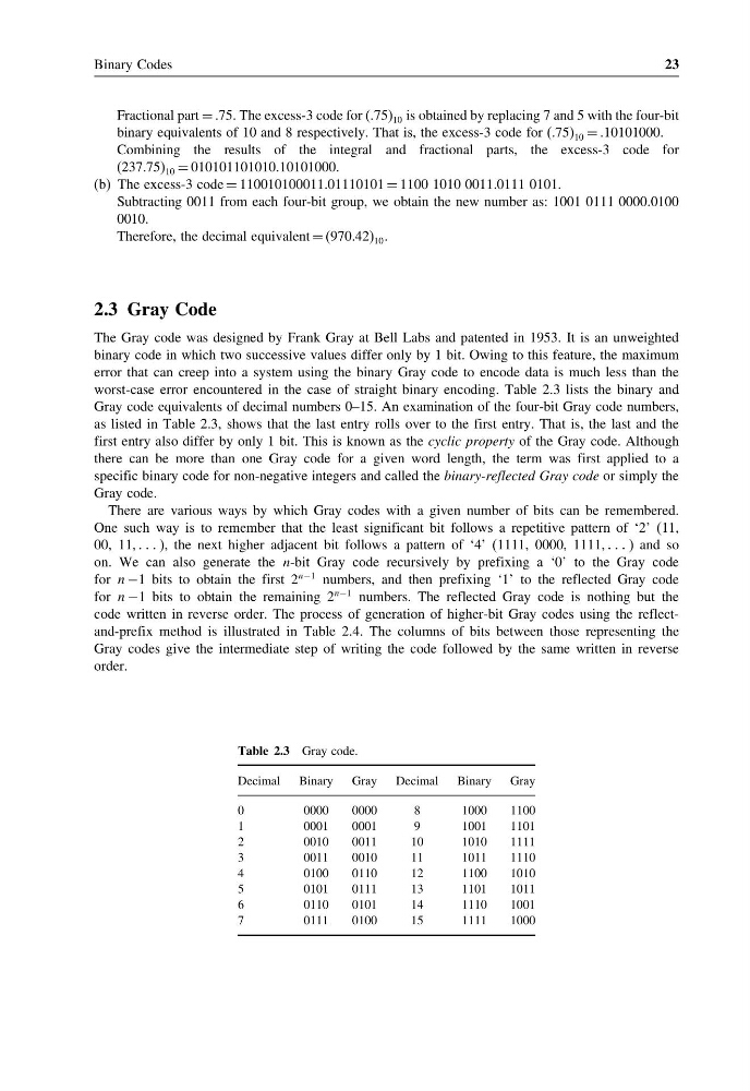
worst-case error encountered in the case of straight binary encoding. Table 2.3 lists the binary and
Gray code equivalents of decimal numbers 0–15. An examination of the four-bit Gray code numbers,
as listed in Table 2.3, shows that the last entry rolls over to the first entry. That is, the last and the
first entry also differ by only 1 bit. This is known as the cyclic property of the Gray code. Although
there can be more than one Gray code for a given word length, the term was first applied to a
specific binary code for non-negative integers and called the binary-reflected Gray code or simply the
Gray code.
There are various ways by which Gray codes with a given number of bits can be remembered.
One such way is to remember that the least significant bit follows a repetitive pattern of ‘2’ (11,
00, 11, ), the next higher adjacent bit follows a pattern of ‘4’ (1111, 0000, 1111, ) and so
on. We can also generate the n-bit Gray code recursively by prefixing a ‘0’ to the Gray code
for n −1 bits to obtain the first 2
n−1 numbers, and then prefixing ‘1’ to the reflected Gray code
for n −1 bits to obtain the remaining 2
n−1 numbers. The reflected Gray code is nothing but the
code written in reverse order. The process of generation of higher-bit Gray codes using the reflectand-prefix method is illustrated in Table 2.4. The columns of bits between those representing the
Gray codes give the intermediate step of writing the code followed by the same written in reverse
order.
Table 2.3 Gray code.
Decimal Binary Gray Decimal Binary Gray
0
0000
0000
8
1000
1100
1
0001
0001
9
1001
1101
2
0010
0011
10
1010
1111
3
0011
0010
11
1011
1110
4
0100
0110
12
1100
1010
5
0101
0111
13
1101
1011
6
0110
0101
14
1110
1001
7
0111
0100
15
1111
1000
23
Fractional part = .75. The excess-3 code for (.75) 10 is obtained by replacing 7 and 5 with the four-bit
binary equivalents of 10 and 8 respectively. That is, the excess-3 code for (.75) 10 = .10101000.
Combining the results of the integral and fractional parts, the excess-3 code for
(237.75) 10 = 010101101010.10101000.
(b) The excess-3 code = 110010100011.01110101 = 1100 1010 0011.0111 0101.
Subtracting 0011 from each four-bit group, we obtain the new number as: 1001 0111 0000.0100
0010.
Therefore, the decimal equivalent = (970.42) 10 .
2.3 Gray Code
The Gray code was designed by Frank Gray at Bell Labs and patented in 1953. It is an unweighted
binary code in which two successive values differ only by 1 bit. Owing to this feature, the maximum
error that can creep into a system using the binary Gray code to encode data is much less than the
worst-case error encountered in the case of straight binary encoding. Table 2.3 lists the binary and
Gray code equivalents of decimal numbers 0–15. An examination of the four-bit Gray code numbers,
as listed in Table 2.3, shows that the last entry rolls over to the first entry. That is, the last and the
first entry also differ by only 1 bit. This is known as the cyclic property of the Gray code. Although
there can be more than one Gray code for a given word length, the term was first applied to a
specific binary code for non-negative integers and called the binary-reflected Gray code or simply the
Gray code.
There are various ways by which Gray codes with a given number of bits can be remembered.
One such way is to remember that the least significant bit follows a repetitive pattern of ‘2’ (11,
00, 11, ), the next higher adjacent bit follows a pattern of ‘4’ (1111, 0000, 1111, ) and so
on. We can also generate the n-bit Gray code recursively by prefixing a ‘0’ to the Gray code
for n −1 bits to obtain the first 2
n−1 numbers, and then prefixing ‘1’ to the reflected Gray code
for n −1 bits to obtain the remaining 2
n−1 numbers. The reflected Gray code is nothing but the
code written in reverse order. The process of generation of higher-bit Gray codes using the reflectand-prefix method is illustrated in Table 2.4. The columns of bits between those representing the
Gray codes give the intermediate step of writing the code followed by the same written in reverse
order.
Table 2.3 Gray code.
Decimal Binary Gray Decimal Binary Gray
0
0000
0000
8
1000
1100
1
0001
0001
9
1001
1101
2
0010
0011
10
1010
1111
3
0011
0010
11
1011
1110
4
0100
0110
12
1100
1010
5
0101
0111
13
1101
1011
6
0110
0101
14
1110
1001
7
0111
0100
15
1111
1000