

292
Digital Electronics
(a) Since both ENABLE inputs are active, the decoder outputs will therefore be active depending upon
the logic status of the input lines. For the given logic status of the input lines, decoder output line
13 will be active and therefore LOW. All other output lines will be inactive and therefore in the
logic HIGH state.
(b) Since neither ENABLE input is active, all decoder outputs will be inactive and in the logic HIGH
state.
(c) The same as (b).
Example 8.10
The decoder of example 8.9 is to be used as a 1-of-16 demultiplexer. A logically compatible pulsed
waveform is to be switched between output line 9 and line 15 when the logic status of an external
control input is LOW and HIGH respectively. Draw the logic diagram indicating the logic status of
ENABLE inputs and DCBA inputs and the point of application of the pulsed waveform.
Solution
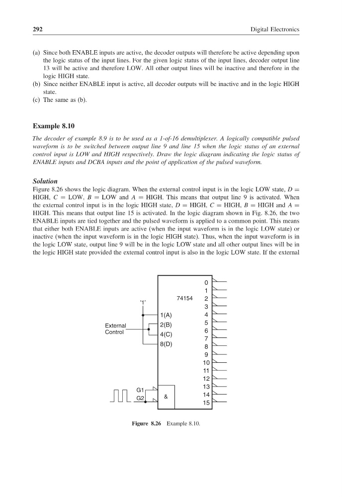
Figure 8.26 shows the logic diagram. When the external control input is in the logic LOW state, D =
HIGH, C = LOW, B = LOW and A = HIGH. This means that output line 9 is activated. When
the external control input is in the logic HIGH state, D = HIGH, C = HIGH, B = HIGH and A =
HIGH. This means that output line 15 is activated. In the logic diagram shown in Fig. 8.26, the two
ENABLE inputs are tied together and the pulsed waveform is applied to a common point. This means
that either both ENABLE inputs are active (when the input waveform is in the logic LOW state) or
inactive (when the input waveform is in the logic HIGH state). Thus, when the input waveform is in
the logic LOW state, output line 9 will be in the logic LOW state and all other output lines will be in
the logic HIGH state provided the external control input is also in the logic LOW state. If the external
0
1
2
3
4
5
6
7
8
9
10
11
12
13
14
15
74154
1(A)
2(B)
4(C)
8(D)
&
External
Control
G1
G2
'1’
Figure 8.26 Example 8.10.
Digital Electronics
(a) Since both ENABLE inputs are active, the decoder outputs will therefore be active depending upon
the logic status of the input lines. For the given logic status of the input lines, decoder output line
13 will be active and therefore LOW. All other output lines will be inactive and therefore in the
logic HIGH state.
(b) Since neither ENABLE input is active, all decoder outputs will be inactive and in the logic HIGH
state.
(c) The same as (b).
Example 8.10
The decoder of example 8.9 is to be used as a 1-of-16 demultiplexer. A logically compatible pulsed
waveform is to be switched between output line 9 and line 15 when the logic status of an external
control input is LOW and HIGH respectively. Draw the logic diagram indicating the logic status of
ENABLE inputs and DCBA inputs and the point of application of the pulsed waveform.
Solution
Figure 8.26 shows the logic diagram. When the external control input is in the logic LOW state, D =
HIGH, C = LOW, B = LOW and A = HIGH. This means that output line 9 is activated. When
the external control input is in the logic HIGH state, D = HIGH, C = HIGH, B = HIGH and A =
HIGH. This means that output line 15 is activated. In the logic diagram shown in Fig. 8.26, the two
ENABLE inputs are tied together and the pulsed waveform is applied to a common point. This means
that either both ENABLE inputs are active (when the input waveform is in the logic LOW state) or
inactive (when the input waveform is in the logic HIGH state). Thus, when the input waveform is in
the logic LOW state, output line 9 will be in the logic LOW state and all other output lines will be in
the logic HIGH state provided the external control input is also in the logic LOW state. If the external
0
1
2
3
4
5
6
7
8
9
10
11
12
13
14
15
74154
1(A)
2(B)
4(C)
8(D)
&
External
Control
G1
G2
'1’
Figure 8.26 Example 8.10.