

Arithmetic Circuits
263
7.9.1 Cascading Magnitude Comparators
As outlined earlier, magnitude comparators available in IC form are designed in such a way that
they can be connected in a cascade arrangement to perform comparison operations on numbers of
longer lengths. In cascade arrangement, the A = B, A > B and A < B outputs of a stage handling
less significant bits are connected to corresponding inputs of the next adjacent stage handling more
significant bits. Also, the stage handling least significant bits must have a HIGH level at the A = B
input. The other two cascading inputs (A > B and A < BB may be connected to a LOW level. We
will illustrate the concept by showing the arrangement of an eight-bit magnitude comparator using two
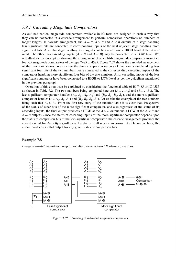
four-bit magnitude comparators of the type 7485 or 4585. Figure 7.37 shows the cascaded arrangement
of the two comparators. We can see the three comparison outputs of the comparator handling less
significant four bits of the two numbers being connected to the corresponding cascading inputs of the
comparator handling more significant four bits of the two numbers. Also, cascading inputs of the less
significant comparator have been connected to a HIGH or LOW level as per the guidelines mentioned
in the previous paragraph.
Operation of this circuit can be explained by considering the functional table of IC 7485 or IC 4585
as shown in Table 7.2. The two numbers being compared here are (A 7 A 0 ) and (B 7 B 0 . The
less significant comparator handles (A 3 , A 2 , A 1 , A 0 and (B 3 , B 2 , B 1 , B 0 , and the more significant
comparator handles (A 7 , A 6 , A 5 , A 4 and (B 7 , B 6 , B 5 , B 4 . Let us take the example of the two numbers
being such that A 7 > B 7 . From the first-row entry of the function table it is clear that, irrespective
of the status of other bits of the more significant comparator, and also regardless of the status of its
cascading inputs, the final output produces a HIGH at the A > B output and a LOW at the A < B and
A = B outputs. Since the status of cascading inputs of the more significant comparator depends upon
the status of comparison bits of the less significant comparator, the cascade arrangement produces the
correct output for A 7 > B 7 regardless of the status of all other comparison bits. On similar lines, the
circuit produces a valid output for any given status of comparison bits.
Example 7.8
Design a two-bit magnitude comparator. Also, write relevant Boolean expressions.
Figure 7.37 Cascading of individual magnitude comparators.
263
7.9.1 Cascading Magnitude Comparators
As outlined earlier, magnitude comparators available in IC form are designed in such a way that
they can be connected in a cascade arrangement to perform comparison operations on numbers of
longer lengths. In cascade arrangement, the A = B, A > B and A < B outputs of a stage handling
less significant bits are connected to corresponding inputs of the next adjacent stage handling more
significant bits. Also, the stage handling least significant bits must have a HIGH level at the A = B
input. The other two cascading inputs (A > B and A < BB may be connected to a LOW level. We
will illustrate the concept by showing the arrangement of an eight-bit magnitude comparator using two
four-bit magnitude comparators of the type 7485 or 4585. Figure 7.37 shows the cascaded arrangement
of the two comparators. We can see the three comparison outputs of the comparator handling less
significant four bits of the two numbers being connected to the corresponding cascading inputs of the
comparator handling more significant four bits of the two numbers. Also, cascading inputs of the less
significant comparator have been connected to a HIGH or LOW level as per the guidelines mentioned
in the previous paragraph.
Operation of this circuit can be explained by considering the functional table of IC 7485 or IC 4585
as shown in Table 7.2. The two numbers being compared here are (A 7 A 0 ) and (B 7 B 0 . The
less significant comparator handles (A 3 , A 2 , A 1 , A 0 and (B 3 , B 2 , B 1 , B 0 , and the more significant
comparator handles (A 7 , A 6 , A 5 , A 4 and (B 7 , B 6 , B 5 , B 4 . Let us take the example of the two numbers
being such that A 7 > B 7 . From the first-row entry of the function table it is clear that, irrespective
of the status of other bits of the more significant comparator, and also regardless of the status of its
cascading inputs, the final output produces a HIGH at the A > B output and a LOW at the A < B and
A = B outputs. Since the status of cascading inputs of the more significant comparator depends upon
the status of comparison bits of the less significant comparator, the cascade arrangement produces the
correct output for A 7 > B 7 regardless of the status of all other comparison bits. On similar lines, the
circuit produces a valid output for any given status of comparison bits.
Example 7.8
Design a two-bit magnitude comparator. Also, write relevant Boolean expressions.
Figure 7.37 Cascading of individual magnitude comparators.