

Logic Gates and Related Devices
107
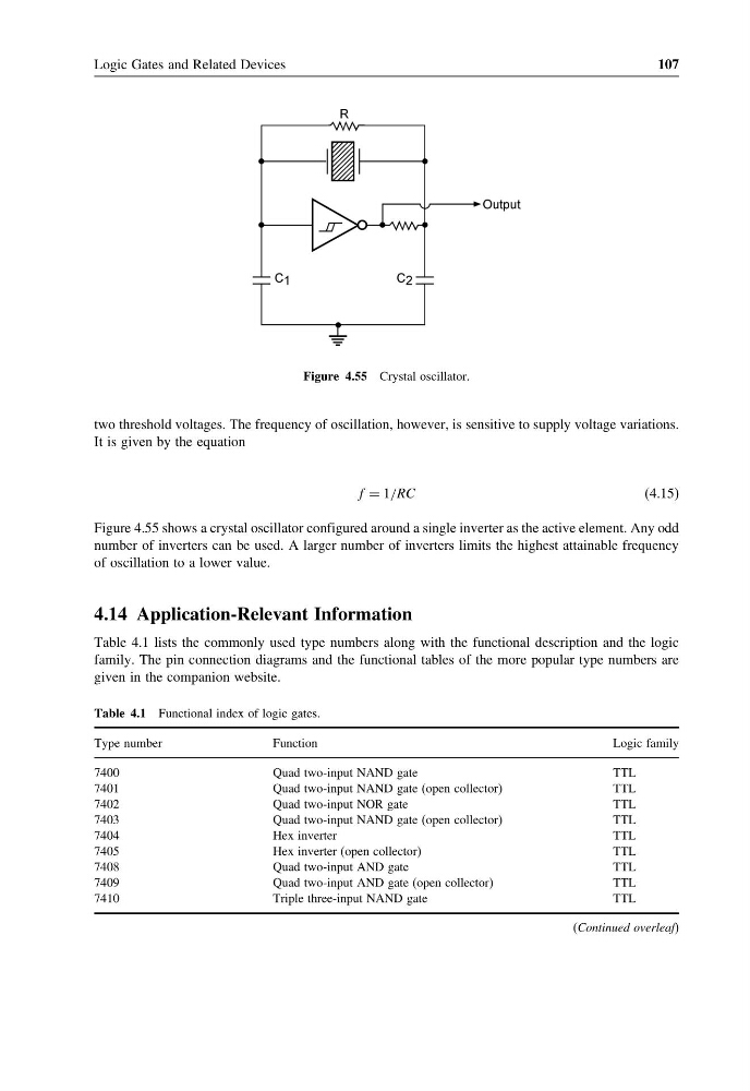
Figure 4.55 Crystal oscillator.
two threshold voltages. The frequency of oscillation, however, is sensitive to supply voltage variations.
It is given by the equation
f = 1/RC
(4.15)
Figure 4.55 shows a crystal oscillator configured around a single inverter as the active element. Any odd
number of inverters can be used. A larger number of inverters limits the highest attainable frequency
of oscillation to a lower value.
4.14 Application-Relevant Information
Table 4.1 lists the commonly used type numbers along with the functional description and the logic
family. The pin connection diagrams and the functional tables of the more popular type numbers are
given in the companion website.
Table 4.1 Functional index of logic gates.
Type number
Function
Logic family
7400
Quad two-input NAND gate
TTL
7401
Quad two-input NAND gate (open collector)
TTL
7402
Quad two-input NOR gate
TTL
7403
Quad two-input NAND gate (open collector)
TTL
7404
Hex inverter
TTL
7405
Hex inverter (open collector)
TTL
7408
Quad two-input AND gate
TTL
7409
Quad two-input AND gate (open collector)
TTL
7410
Triple three-input NAND gate
TTL
(Continued overleaf)
107
Figure 4.55 Crystal oscillator.
two threshold voltages. The frequency of oscillation, however, is sensitive to supply voltage variations.
It is given by the equation
f = 1/RC
(4.15)
Figure 4.55 shows a crystal oscillator configured around a single inverter as the active element. Any odd
number of inverters can be used. A larger number of inverters limits the highest attainable frequency
of oscillation to a lower value.
4.14 Application-Relevant Information
Table 4.1 lists the commonly used type numbers along with the functional description and the logic
family. The pin connection diagrams and the functional tables of the more popular type numbers are
given in the companion website.
Table 4.1 Functional index of logic gates.
Type number
Function
Logic family
7400
Quad two-input NAND gate
TTL
7401
Quad two-input NAND gate (open collector)
TTL
7402
Quad two-input NOR gate
TTL
7403
Quad two-input NAND gate (open collector)
TTL
7404
Hex inverter
TTL
7405
Hex inverter (open collector)
TTL
7408
Quad two-input AND gate
TTL
7409
Quad two-input AND gate (open collector)
TTL
7410
Triple three-input NAND gate
TTL
(Continued overleaf)