

104
Digital Electronics
4.13.2 AND Gate
An AND gate is commonly used as an ENABLE or INHIBIT gate to allow or disallow passage of
data from one point in the circuit to another. One such application of enabling operation, for instance,
is in the measurement of the frequency of a pulsed waveform or the width of a given pulse with the
help of a counter. In the case of frequency measurement, a gating pulse of known width is used to
enable the passage of the pulse waveform to the counter’s clock input. In the case of pulse width
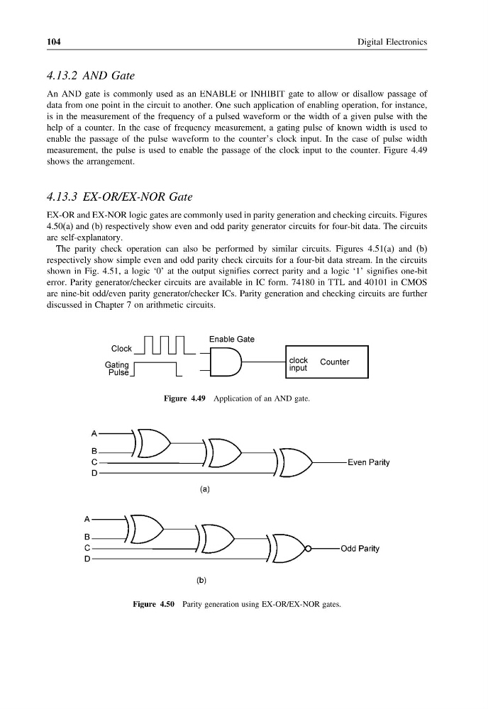
measurement, the pulse is used to enable the passage of the clock input to the counter. Figure 4.49
shows the arrangement.
4.13.3 EX-OR/EX-NOR Gate
EX-OR and EX-NOR logic gates are commonly used in parity generation and checking circuits. Figures
4.50(a) and (b) respectively show even and odd parity generator circuits for four-bit data. The circuits
are self-explanatory.
The parity check operation can also be performed by similar circuits. Figures 4.51(a) and (b)
respectively show simple even and odd parity check circuits for a four-bit data stream. In the circuits
shown in Fig. 4.51, a logic ‘0’ at the output signifies correct parity and a logic ‘1’ signifies one-bit
error. Parity generator/checker circuits are available in IC form. 74180 in TTL and 40101 in CMOS
are nine-bit odd/even parity generator/checker ICs. Parity generation and checking circuits are further
discussed in Chapter 7 on arithmetic circuits.
Figure 4.49 Application of an AND gate.
Figure 4.50 Parity generation using EX-OR/EX-NOR gates.
Digital Electronics
4.13.2 AND Gate
An AND gate is commonly used as an ENABLE or INHIBIT gate to allow or disallow passage of
data from one point in the circuit to another. One such application of enabling operation, for instance,
is in the measurement of the frequency of a pulsed waveform or the width of a given pulse with the
help of a counter. In the case of frequency measurement, a gating pulse of known width is used to
enable the passage of the pulse waveform to the counter’s clock input. In the case of pulse width
measurement, the pulse is used to enable the passage of the clock input to the counter. Figure 4.49
shows the arrangement.
4.13.3 EX-OR/EX-NOR Gate
EX-OR and EX-NOR logic gates are commonly used in parity generation and checking circuits. Figures
4.50(a) and (b) respectively show even and odd parity generator circuits for four-bit data. The circuits
are self-explanatory.
The parity check operation can also be performed by similar circuits. Figures 4.51(a) and (b)
respectively show simple even and odd parity check circuits for a four-bit data stream. In the circuits
shown in Fig. 4.51, a logic ‘0’ at the output signifies correct parity and a logic ‘1’ signifies one-bit
error. Parity generator/checker circuits are available in IC form. 74180 in TTL and 40101 in CMOS
are nine-bit odd/even parity generator/checker ICs. Parity generation and checking circuits are further
discussed in Chapter 7 on arithmetic circuits.
Figure 4.49 Application of an AND gate.
Figure 4.50 Parity generation using EX-OR/EX-NOR gates.