

electrolyte layer thickness ranging from 1 to 10 μm. In the first step a reflectivity
spectrum of the empty spectroelectrochemical cell is measured. The critical angle of
the CaF 2 |air interface is equal to 49
. Thus, at the angle of incidence higher than the
critical angle of the CaF 2 |air interface (φ i ¼ 53
) the IR beam is totally reflected from
the inner prism surface. This reflectivity spectrum serves as a measure of the
intensity of the incoming IR radiation (I i ). In the next step, the
spectroelectrochemical cell is filled with the solution and a reflectance spectrum at
the same φ i is measured. The thickness of the electrolyte layer between the gold
surface and CaF 2 window can be adjusted via a micrometric screw built in the
spectroelectrochemical cell (Fig. 2.6). The spectrum of the IR light transmitted
through the CaF 2 and D 2 O phases and reflected from the gold surface is measured
(I r ). The ratio of I r /I i provides the reflectivity spectrum of the thin layer
spectroelectrochemical cell (red line, Fig. 2.7). The best fit of the experimentally
measured reflectivity spectrum to the calculated spectra allows the determination of
the thickness of the electrolyte layer. In the example shown in Fig. 2.7 the electrolyte
layer thickness is equal to 5.4 Æ 0.4 μm.
The spectroelectrochemical cell can be mounted in the experimental chamber
either in a vertical or horizontal position [3, 22, 27]. In both cases the polarizers and
mirrors on the optical path have to be adjusted to achieve the required angles of
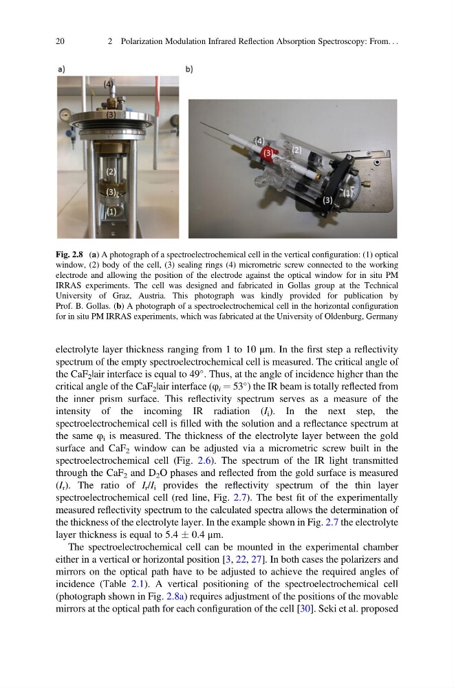
incidence (Table 2.1). A vertical positioning of the spectroelectrochemical cell
(photograph shown in Fig. 2.8a) requires adjustment of the positions of the movable
mirrors at the optical path for each configuration of the cell [30]. Seki et al. proposed
Fig. 2.8 (a) A photograph of a spectroelectrochemical cell in the vertical configuration: (1) optical
window, (2) body of the cell, (3) sealing rings (4) micrometric screw connected to the working
electrode and allowing the position of the electrode against the optical window for in situ PM
IRRAS experiments. The cell was designed and fabricated in Gollas group at the Technical
University of Graz, Austria. This photograph was kindly provided for publication by
Prof. B. Gollas. (b) A photograph of a spectroelectrochemical cell in the horizontal configuration
for in situ PM IRRAS experiments, which was fabricated at the University of Oldenburg, Germany
20
2 Polarization Modulation Infrared Reflection Absorption Spectroscopy: From. . .
spectrum of the empty spectroelectrochemical cell is measured. The critical angle of
the CaF 2 |air interface is equal to 49
. Thus, at the angle of incidence higher than the
critical angle of the CaF 2 |air interface (φ i ¼ 53
) the IR beam is totally reflected from
the inner prism surface. This reflectivity spectrum serves as a measure of the
intensity of the incoming IR radiation (I i ). In the next step, the
spectroelectrochemical cell is filled with the solution and a reflectance spectrum at
the same φ i is measured. The thickness of the electrolyte layer between the gold
surface and CaF 2 window can be adjusted via a micrometric screw built in the
spectroelectrochemical cell (Fig. 2.6). The spectrum of the IR light transmitted
through the CaF 2 and D 2 O phases and reflected from the gold surface is measured
(I r ). The ratio of I r /I i provides the reflectivity spectrum of the thin layer
spectroelectrochemical cell (red line, Fig. 2.7). The best fit of the experimentally
measured reflectivity spectrum to the calculated spectra allows the determination of
the thickness of the electrolyte layer. In the example shown in Fig. 2.7 the electrolyte
layer thickness is equal to 5.4 Æ 0.4 μm.
The spectroelectrochemical cell can be mounted in the experimental chamber
either in a vertical or horizontal position [3, 22, 27]. In both cases the polarizers and
mirrors on the optical path have to be adjusted to achieve the required angles of
incidence (Table 2.1). A vertical positioning of the spectroelectrochemical cell
(photograph shown in Fig. 2.8a) requires adjustment of the positions of the movable
mirrors at the optical path for each configuration of the cell [30]. Seki et al. proposed
Fig. 2.8 (a) A photograph of a spectroelectrochemical cell in the vertical configuration: (1) optical
window, (2) body of the cell, (3) sealing rings (4) micrometric screw connected to the working
electrode and allowing the position of the electrode against the optical window for in situ PM
IRRAS experiments. The cell was designed and fabricated in Gollas group at the Technical
University of Graz, Austria. This photograph was kindly provided for publication by
Prof. B. Gollas. (b) A photograph of a spectroelectrochemical cell in the horizontal configuration
for in situ PM IRRAS experiments, which was fabricated at the University of Oldenburg, Germany
20
2 Polarization Modulation Infrared Reflection Absorption Spectroscopy: From. . .