

For the distributed model, as the number of elements
increases, the area of each membrane element decreases, and
the log means used in the short-cut method approximate to
the respective arithmetic means. Therefore, in MPd-UOE, it
was considered that for a number of elements equal or higher
than 10, and the log means are replaced by arithmetic means.
3.1.2 Lumped Model Algorithm: MPx-UOE
The algorithm for MPx-UOE model comprises five steps,
which are described below: [S1] Input data; [S2] Parameters
for energy balance; [S3] Initial values for NRM; [S4]
Lumped permeation and energy balance calculations; [S5]
Returning product data to simulation.
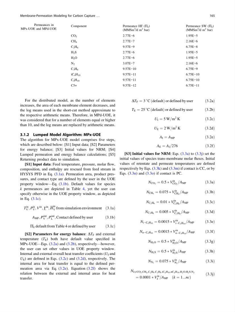
[S1] Input data: Feed temperature, pressure, molar flow,
composition, and enthalpy are rescued from feed stream in
HYSYS PFD in Eq. (3.1a). Permeation area, product pressures, and contact type are defined by the user in the UOE
property window—Eq. (3.1b). Default values for species
k permeances are depicted in Table 4, yet the user can
specify otherwise in the UOE property window, as depicted
in Eq. (3.1c).
T
in
V ; P
in
V ; V
in
; Y
in
; H
in
V from simulation environment ð3:1aÞ
A MP ; P
out
V ; P
out
L ; Contact defined by user
ð3:1bÞ
P k default from Table 4 or defined by user
ð3:1cÞ
[S2] Parameters for energy balance: DT F and external
temperature (T E ) both have default value specified in
MPx-UOE—Eqs. (3.2a) and (3.2b), respectively—however,
the user can set other values in UOE property window.
Internal and external overall heat transfer coefficients (U I and
U E ) are defined in Eqs. (3.2c) and (3.2d), respectively. The
internal area for heat transfer is equal to the defined permeation area via Eq. (3.2e). Equation (3.2f) shows the
relation between the external and internal areas for heat
transfer.
DT F ¼ 3
C ðdefaultÞ or defined by user
ð3:2aÞ
T E ¼ 25
C ðdefaultÞ or defined by user
ð3:2bÞ
U I ¼ 5 W=m
2
K
ð3:2cÞ
U E ¼ 2 W=m
2
K
ð3:2dÞ
A I ¼ A MP
ð3:2eÞ
A E ¼ A I =276
ð3:2fÞ
[S3] Initial values for NRM: Eqs. (3.3a) to (3.3j) set the
initial values of species trans-membrane molar fluxes. Initial
values of retentate and permeate temperatures are defined
respectively by Eqs. (3.3k) and (3.3m) if contact is CC, or by
Eqs. (3.3n) and (3.3o) if contact is PC.
N CO 2 ¼ 0:5 Ã V
in
CO 2
=A MP
ð3:3aÞ
N CH 4 ¼ 0:075 Ã V
in
CH 4
=A MP
ð3:3bÞ
N C 2 H 6 ¼ 0:01 Ã V
in
C 2 H 6
=A MP
ð3:3cÞ
N C 3 H 8 ¼ 0:005 Ã V
in
C 3 H 8
=A MP
ð3:3dÞ
N iÀC 4 H 10 ¼ 0:0015 Ã V
in
iÀC 4 H 10
=A MP
ð3:3eÞ
N nÀC 4 H 10 ¼ 0:0015 Ã V
in
nÀC 4 H 10
=A MP
ð3:3fÞ
N H 2 O ¼ 0:5 Ã V
in
H 2 O =A MP
ð3:3gÞ
N H 2 S ¼ 0:5 Ã V
in
H 2 S =A MP
ð3:3hÞ
N N 2 ¼ 0:075 Ã V
in
N 2
=A MP
ð3:3iÞ
N k6 ¼CO 2 ;CH 4 ;C 2 H 6 ;C 3 H 8 ;iC 4 H 10 ;nC 4 H 10 ;H 2 O;H 2 S;N 2
¼ 0:0001 Ã V
in
k =A MP ðk ¼ 1:::ncÞ
ð3:3jÞ
Table 4 Permeances in
MPx-UOE and MPd-UOE
Component
Permeance HF (P k )
(MMSm
3
/d m
2 bar)
Permeance SW (P k )
(MMSm
3 /d m
2 bar)
CO 2
2.77E−6
1.95E−5
CH 4
2.77E−7
2.16E−6
C 2 H 6
9.57E−9
6.75E−8
H 2 S
2.77E−6
1.95E−5
H 2 O
2.77E−6
1.95E−5
N 2
3.07E−7
2.16E−6
C 3 H 8
9.57E−10
6.75E−9
iC 4 H 10
9.57E−11
6.75E−10
C 4 H 10
9.57E−11
6.75E−10
C5+
9.57E−12
6.75E−11
Membrane-Permeation Modeling for Carbon Capture …
165
increases, the area of each membrane element decreases, and
the log means used in the short-cut method approximate to
the respective arithmetic means. Therefore, in MPd-UOE, it
was considered that for a number of elements equal or higher
than 10, and the log means are replaced by arithmetic means.
3.1.2 Lumped Model Algorithm: MPx-UOE
The algorithm for MPx-UOE model comprises five steps,
which are described below: [S1] Input data; [S2] Parameters
for energy balance; [S3] Initial values for NRM; [S4]
Lumped permeation and energy balance calculations; [S5]
Returning product data to simulation.
[S1] Input data: Feed temperature, pressure, molar flow,
composition, and enthalpy are rescued from feed stream in
HYSYS PFD in Eq. (3.1a). Permeation area, product pressures, and contact type are defined by the user in the UOE
property window—Eq. (3.1b). Default values for species
k permeances are depicted in Table 4, yet the user can
specify otherwise in the UOE property window, as depicted
in Eq. (3.1c).
T
in
V ; P
in
V ; V
in
; Y
in
; H
in
V from simulation environment ð3:1aÞ
A MP ; P
out
V ; P
out
L ; Contact defined by user
ð3:1bÞ
P k default from Table 4 or defined by user
ð3:1cÞ
[S2] Parameters for energy balance: DT F and external
temperature (T E ) both have default value specified in
MPx-UOE—Eqs. (3.2a) and (3.2b), respectively—however,
the user can set other values in UOE property window.
Internal and external overall heat transfer coefficients (U I and
U E ) are defined in Eqs. (3.2c) and (3.2d), respectively. The
internal area for heat transfer is equal to the defined permeation area via Eq. (3.2e). Equation (3.2f) shows the
relation between the external and internal areas for heat
transfer.
DT F ¼ 3
C ðdefaultÞ or defined by user
ð3:2aÞ
T E ¼ 25
C ðdefaultÞ or defined by user
ð3:2bÞ
U I ¼ 5 W=m
2
K
ð3:2cÞ
U E ¼ 2 W=m
2
K
ð3:2dÞ
A I ¼ A MP
ð3:2eÞ
A E ¼ A I =276
ð3:2fÞ
[S3] Initial values for NRM: Eqs. (3.3a) to (3.3j) set the
initial values of species trans-membrane molar fluxes. Initial
values of retentate and permeate temperatures are defined
respectively by Eqs. (3.3k) and (3.3m) if contact is CC, or by
Eqs. (3.3n) and (3.3o) if contact is PC.
N CO 2 ¼ 0:5 Ã V
in
CO 2
=A MP
ð3:3aÞ
N CH 4 ¼ 0:075 Ã V
in
CH 4
=A MP
ð3:3bÞ
N C 2 H 6 ¼ 0:01 Ã V
in
C 2 H 6
=A MP
ð3:3cÞ
N C 3 H 8 ¼ 0:005 Ã V
in
C 3 H 8
=A MP
ð3:3dÞ
N iÀC 4 H 10 ¼ 0:0015 Ã V
in
iÀC 4 H 10
=A MP
ð3:3eÞ
N nÀC 4 H 10 ¼ 0:0015 Ã V
in
nÀC 4 H 10
=A MP
ð3:3fÞ
N H 2 O ¼ 0:5 Ã V
in
H 2 O =A MP
ð3:3gÞ
N H 2 S ¼ 0:5 Ã V
in
H 2 S =A MP
ð3:3hÞ
N N 2 ¼ 0:075 Ã V
in
N 2
=A MP
ð3:3iÞ
N k6 ¼CO 2 ;CH 4 ;C 2 H 6 ;C 3 H 8 ;iC 4 H 10 ;nC 4 H 10 ;H 2 O;H 2 S;N 2
¼ 0:0001 Ã V
in
k =A MP ðk ¼ 1:::ncÞ
ð3:3jÞ
Table 4 Permeances in
MPx-UOE and MPd-UOE
Component
Permeance HF (P k )
(MMSm
3
/d m
2 bar)
Permeance SW (P k )
(MMSm
3 /d m
2 bar)
CO 2
2.77E−6
1.95E−5
CH 4
2.77E−7
2.16E−6
C 2 H 6
9.57E−9
6.75E−8
H 2 S
2.77E−6
1.95E−5
H 2 O
2.77E−6
1.95E−5
N 2
3.07E−7
2.16E−6
C 3 H 8
9.57E−10
6.75E−9
iC 4 H 10
9.57E−11
6.75E−10
C 4 H 10
9.57E−11
6.75E−10
C5+
9.57E−12
6.75E−11
Membrane-Permeation Modeling for Carbon Capture …
165