

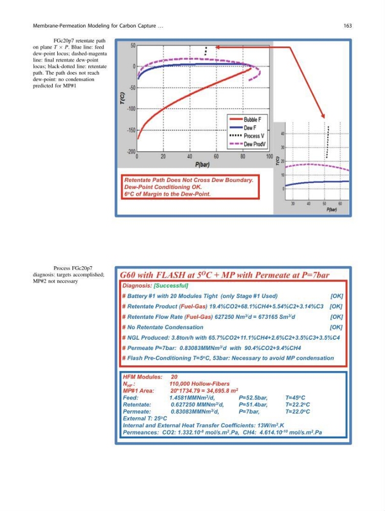
Retentate Path Does Not Cross Dew Boundary.
Dew-Point Conditioning OK.
6 o C of Margin to the Dew-Point.
Fig. 19 FGc20p7 retentate path
on plane T Â P. Blue line: feed
dew-point locus; dashed-magenta
line: final retentate dew-point
locus; black-dotted line: retentate
path. The path does not reach
dew-point: no condensation
predicted for MP#1
HFM Modules: 20
N HF :
110,000 Hollow-Fibers
MP#1 Area:
20*1734.79 = 34,695.8 m 2
Feed:
1.4581MMNm 3 /d,
P=52.5bar,
T=45 o C
Retentate:
0.627250 MMNm 3/ d,
P=51.4bar,
T=22.2 o C
Permeate:
0.83083MMNm 3/ d,
P=7bar,
T=22.0 o C
External T: 25 o C
Internal and External Heat Transfer Coefficients: 13W/m 2 .K
Permeances: CO2: 1.332.10 -8 mol/s.m 2 .Pa, CH4: 4.614.10 -10 mol/s.m 2 .Pa
G60 with FLASH at 5 O C + MP with Permeate at P=7bar
Diagnosis: [Successful]
# Battery #1 with 20 Modules Tight (only Stage #1 Used)
[OK]
# Retentate Product (Fuel-Gas) 19.4%CO2+68.1%CH4+5.54%C2+3.14%C3 [OK]
# Retentate Flow Rate (Fuel-Gas) 627250 Nm 3/ d = 673165 Sm 3/ d
[OK]
# No Retentate Condensation
[OK]
# NGL Produced: 3.8ton/h with 65.7%CO2+11.1%CH4+2.6%C2+3.5%C3+3.5%C4
# Permeate P=7bar: 0.83083MMNm 3/ d with 90.4%CO2+9.4%CH4
# Flash Pre-Conditioning T=5 o C, 53bar: Necessary to avoid MP condensation
Fig. 20 Process FGc20p7
diagnosis: targets accomplished;
MP#2 not necessary
Membrane-Permeation Modeling for Carbon Capture …
163
Dew-Point Conditioning OK.
6 o C of Margin to the Dew-Point.
Fig. 19 FGc20p7 retentate path
on plane T Â P. Blue line: feed
dew-point locus; dashed-magenta
line: final retentate dew-point
locus; black-dotted line: retentate
path. The path does not reach
dew-point: no condensation
predicted for MP#1
HFM Modules: 20
N HF :
110,000 Hollow-Fibers
MP#1 Area:
20*1734.79 = 34,695.8 m 2
Feed:
1.4581MMNm 3 /d,
P=52.5bar,
T=45 o C
Retentate:
0.627250 MMNm 3/ d,
P=51.4bar,
T=22.2 o C
Permeate:
0.83083MMNm 3/ d,
P=7bar,
T=22.0 o C
External T: 25 o C
Internal and External Heat Transfer Coefficients: 13W/m 2 .K
Permeances: CO2: 1.332.10 -8 mol/s.m 2 .Pa, CH4: 4.614.10 -10 mol/s.m 2 .Pa
G60 with FLASH at 5 O C + MP with Permeate at P=7bar
Diagnosis: [Successful]
# Battery #1 with 20 Modules Tight (only Stage #1 Used)
[OK]
# Retentate Product (Fuel-Gas) 19.4%CO2+68.1%CH4+5.54%C2+3.14%C3 [OK]
# Retentate Flow Rate (Fuel-Gas) 627250 Nm 3/ d = 673165 Sm 3/ d
[OK]
# No Retentate Condensation
[OK]
# NGL Produced: 3.8ton/h with 65.7%CO2+11.1%CH4+2.6%C2+3.5%C3+3.5%C4
# Permeate P=7bar: 0.83083MMNm 3/ d with 90.4%CO2+9.4%CH4
# Flash Pre-Conditioning T=5 o C, 53bar: Necessary to avoid MP condensation
Fig. 20 Process FGc20p7
diagnosis: targets accomplished;
MP#2 not necessary
Membrane-Permeation Modeling for Carbon Capture …
163