

conventional acceleration 91
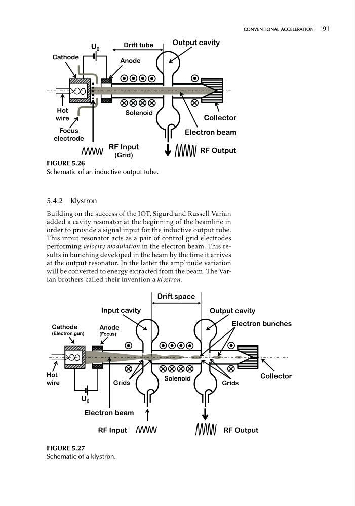
FIGURE 5.26
Schematic of an inductive output tube.
5.4.2 Klystron
Building on the success of the IOT, Sigurd and Russell Varian
added a cavity resonator at the beginning of the beamline in
order to provide a signal input for the inductive output tube.
This input resonator acts as a pair of control grid electrodes
performing velocity modulation in the electron beam. This results in bunching developed in the beam by the time it arrives
at the output resonator. In the latter the amplitude variation
will be converted to energy extracted from the beam. The Varian brothers called their invention a klystron.
FIGURE 5.27
Schematic of a klystron.
FIGURE 5.26
Schematic of an inductive output tube.
5.4.2 Klystron
Building on the success of the IOT, Sigurd and Russell Varian
added a cavity resonator at the beginning of the beamline in
order to provide a signal input for the inductive output tube.
This input resonator acts as a pair of control grid electrodes
performing velocity modulation in the electron beam. This results in bunching developed in the beam by the time it arrives
at the output resonator. In the latter the amplitude variation
will be converted to energy extracted from the beam. The Varian brothers called their invention a klystron.
FIGURE 5.27
Schematic of a klystron.