

conventional acceleration 89
where P RF is the RF power supplied to the cavity, l is
the length of the accelerating structure, R s is the shunt
impedance and K is a correction factor (typically ≈ 0.8).
In accelerators such as drift tube linacs, a so-called
“transit-time factor” also plays a role and needs to be taken
into account in order to evaluate the average energy gain.
Consider an accelerating gap corresponding to the space
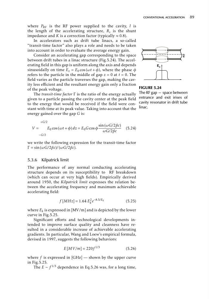
between drift tubes in a linac structure (Fig.5.24). The accelerating field in this gap is uniform along the axis and depends
sinusoidally on time E z = E 0 cos (ωt + φ), where the phase φ
refers to the particle in the middle of gap z = 0 at t = 0. The
field varies as the particle traverses the gap, making the cavity less efficient and the resultant energy gain only a fraction
of the peak voltage.
The transit-time factor Γ is the ratio of the energy actually
given to a particle passing the cavity center at the peak field
to the energy that would be received if the field were constant with time at its peak value. Taking into account that the
energy gained over the gap G is:
+G/2
sin (ωG/2βc)
V =
E 0 cos (ωt + φ) dz = E 0 G cos φ
(5.24)
ωG/2βc
−G/2
we write the following expression for the transit-time factor
Γ = sin (ωG/2βc)/ (ωG/2βc).
5.3.6 Kilpatrick limit
The performance of any normal conducting accelerating
structure depends on its susceptibility to RF breakdown
(which can occur at very high fields). Empirically derived
around 1950, the Kilpatrick limit expresses the relation between the accelerating frequency and maximum achievable
accelerating field:
f [MHz] = 1.64
2
E k e
−8.5/E k
(5.25)
where E k is expressed in [MV/m] and is depicted by the lower
curve in Fig.5.25.
Significant efforts and technological developments intended to improve surface quality and cleanness have resulted in a considerable increase of achievable accelerating
gradients. In particular, Wang and Loew’s empirical formula,
devised in 1997, suggests the following behaviors:
E [MV /m] = 220f
1/3
(5.26)
where f is expressed in [GHz] — shown by the upper curve
in Fig.5.25.
The E ∼ f 1/3 dependence in Eq.5.26 was, for a long time,
( ]
]
GURE 5.24
e RF gap — space between
trance and exit irises of
vity resonator in drift tube
ac.
FI
Th
en
ca
lin
where P RF is the RF power supplied to the cavity, l is
the length of the accelerating structure, R s is the shunt
impedance and K is a correction factor (typically ≈ 0.8).
In accelerators such as drift tube linacs, a so-called
“transit-time factor” also plays a role and needs to be taken
into account in order to evaluate the average energy gain.
Consider an accelerating gap corresponding to the space
between drift tubes in a linac structure (Fig.5.24). The accelerating field in this gap is uniform along the axis and depends
sinusoidally on time E z = E 0 cos (ωt + φ), where the phase φ
refers to the particle in the middle of gap z = 0 at t = 0. The
field varies as the particle traverses the gap, making the cavity less efficient and the resultant energy gain only a fraction
of the peak voltage.
The transit-time factor Γ is the ratio of the energy actually
given to a particle passing the cavity center at the peak field
to the energy that would be received if the field were constant with time at its peak value. Taking into account that the
energy gained over the gap G is:
+G/2
sin (ωG/2βc)
V =
E 0 cos (ωt + φ) dz = E 0 G cos φ
(5.24)
ωG/2βc
−G/2
we write the following expression for the transit-time factor
Γ = sin (ωG/2βc)/ (ωG/2βc).
5.3.6 Kilpatrick limit
The performance of any normal conducting accelerating
structure depends on its susceptibility to RF breakdown
(which can occur at very high fields). Empirically derived
around 1950, the Kilpatrick limit expresses the relation between the accelerating frequency and maximum achievable
accelerating field:
f [MHz] = 1.64
2
E k e
−8.5/E k
(5.25)
where E k is expressed in [MV/m] and is depicted by the lower
curve in Fig.5.25.
Significant efforts and technological developments intended to improve surface quality and cleanness have resulted in a considerable increase of achievable accelerating
gradients. In particular, Wang and Loew’s empirical formula,
devised in 1997, suggests the following behaviors:
E [MV /m] = 220f
1/3
(5.26)
where f is expressed in [GHz] — shown by the upper curve
in Fig.5.25.
The E ∼ f 1/3 dependence in Eq.5.26 was, for a long time,
( ]
]
GURE 5.24
e RF gap — space between
trance and exit irises of
vity resonator in drift tube
ac.
FI
Th
en
ca
lin