

240
An Introduction to Beam Physics
t
E
t
qV
t
E
t
E
t
n
just before cavity
buncher cavity
just after cavity
further downstream
density profile
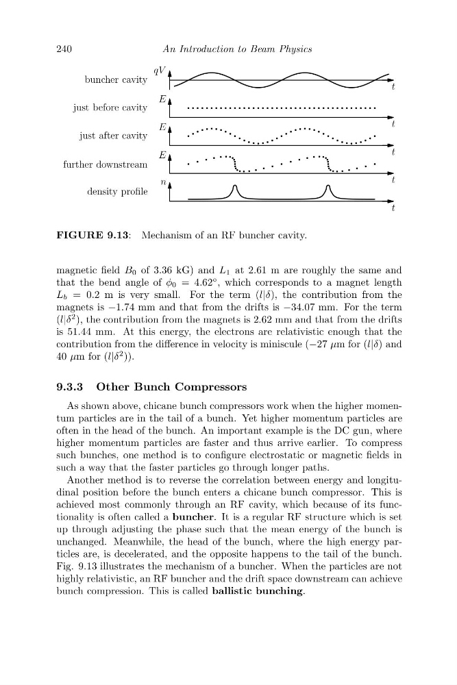
FIGURE 9.13: Mechanism of an RF buncher cavity.
magnetic field B 0 of 3.36 kG) and L 1 at 2.61 m are roughly the same and
that the bend angle of φ 0 = 4.62
◦ , which corresponds to a magnet length
L b = 0.2 m is very small. For the term (l|δ), the contribution from the
magnets is −1.74 mm and that from the drifts is −34.07 mm. For the term
(l|δ
2 ), the contribution from the magnets is 2.62 mm and that from the drifts
is 51.44 mm. At this energy, the electrons are relativistic enough that the
contribution from the difference in velocity is miniscule (−27 μm for (l|δ) and
40 μm for (l|δ
2 )).
9.3.3 Other Bunch Compressors
As shown above, chicane bunch compressors work when the higher momentum particles are in the tail of a bunch. Yet higher momentum particles are
often in the head of the bunch. An important example is the DC gun, where
higher momentum particles are faster and thus arrive earlier. To compress
such bunches, one method is to configure electrostatic or magnetic fields in
such a way that the faster particles go through longer paths.
Another method is to reverse the correlation between energy and longitudinal position before the bunch enters a chicane bunch compressor. This is
achieved most commonly through an RF cavity, which because of its functionality is often called a buncher. It is a regular RF structure which is set
up through adjusting the phase such that the mean energy of the bunch is
unchanged. Meanwhile, the head of the bunch, where the high energy particles are, is decelerated, and the opposite happens to the tail of the bunch.
Fig. 9.13 illustrates the mechanism of a buncher. When the particles are not
highly relativistic, an RF buncher and the drift space downstream can achieve
bunch compression. This is called ballistic bunching.
An Introduction to Beam Physics
t
E
t
qV
t
E
t
E
t
n
just before cavity
buncher cavity
just after cavity
further downstream
density profile
FIGURE 9.13: Mechanism of an RF buncher cavity.
magnetic field B 0 of 3.36 kG) and L 1 at 2.61 m are roughly the same and
that the bend angle of φ 0 = 4.62
◦ , which corresponds to a magnet length
L b = 0.2 m is very small. For the term (l|δ), the contribution from the
magnets is −1.74 mm and that from the drifts is −34.07 mm. For the term
(l|δ
2 ), the contribution from the magnets is 2.62 mm and that from the drifts
is 51.44 mm. At this energy, the electrons are relativistic enough that the
contribution from the difference in velocity is miniscule (−27 μm for (l|δ) and
40 μm for (l|δ
2 )).
9.3.3 Other Bunch Compressors
As shown above, chicane bunch compressors work when the higher momentum particles are in the tail of a bunch. Yet higher momentum particles are
often in the head of the bunch. An important example is the DC gun, where
higher momentum particles are faster and thus arrive earlier. To compress
such bunches, one method is to configure electrostatic or magnetic fields in
such a way that the faster particles go through longer paths.
Another method is to reverse the correlation between energy and longitudinal position before the bunch enters a chicane bunch compressor. This is
achieved most commonly through an RF cavity, which because of its functionality is often called a buncher. It is a regular RF structure which is set
up through adjusting the phase such that the mean energy of the bunch is
unchanged. Meanwhile, the head of the bunch, where the high energy particles are, is decelerated, and the opposite happens to the tail of the bunch.
Fig. 9.13 illustrates the mechanism of a buncher. When the particles are not
highly relativistic, an RF buncher and the drift space downstream can achieve
bunch compression. This is called ballistic bunching.