

R
g
R
1 – ε 1
q R = 0
A 1 e 1
1
A 1 e g1
1
A 1 F 1 t 1gR
1 – ε R
A R e R
A R e gR
E bR
E bg
E b1
R
1
J 1
J R
1
E bg
R
A 1 ε 1
A 1 F 12 τ 1g2
A 1 ε 1
1
b
E
R
J
1
1
R gR
A ε
2
b
E
1 − ε1
A 1 F 1R τ 1gR
A 2 F 2R τ 2gR
J 2
1 − ε1
1
A 2 ε g2
1
A 1 ε g1
J 1
1
1
2
1
g
R
288
Analytical Heat Transfer
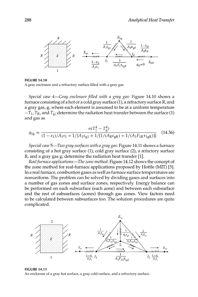
FIGURE 14.10
A gray enclosure and a refractory surface filled with a gray gas.
Special case 4—Gray enclosure filled with a gray gas: Figure 14.10 shows a
furnace consisting of a hot or a cold gray surface (1), a refractory surface R, and
a gray gas, g, where each element is assumed to be at a uniform temperature
−T 1 , T R , and T g ; determine the radiation heat transfer between the surface (1)
and gas as
σ(T 1
4 − T 4 )
q 1g =
g
(14.36)
(1 − ε 1 )/A 1 ε 1 + 1/{A 1 ε g1 + 1/[1/(A R ε gR ) + 1/(A 1 F 1R τ 1gR )]}
Special case 5—Two gray surfaces with a gray gas: Figure 14.11 shows a furnace
consisting of a hot gray surface (1), cold gray surface (2), a refactory surface
R, and a gray gas g; determine the radiation heat transfer [1].
Real furnace applications—The zone method: Figure 14.12 shows the concept of
the zone method for real-furnace applications proposed by Hottle (MIT) [5].
In a real furnace, combustion gases as well as furnace surface temperatures are
nonuniform. The problem can be solved by dividing gases and surfaces into
a number of gas zones and surface zones, respectively. Energy balance can
be performed on each subsurface (each zone) and between each subsurface
and the rest of subsurfaces (zones) through gas zones. View factors need
to be calculated between subsurfaces too. The solution procedures are quite
complicated.
FIGURE 14.11
An enclosure of a gray hot surface, a gray cold surface, and a refractory surface.
g
R
1 – ε 1
q R = 0
A 1 e 1
1
A 1 e g1
1
A 1 F 1 t 1gR
1 – ε R
A R e R
A R e gR
E bR
E bg
E b1
R
1
J 1
J R
1
E bg
R
A 1 ε 1
A 1 F 12 τ 1g2
A 1 ε 1
1
b
E
R
J
1
1
R gR
A ε
2
b
E
1 − ε1
A 1 F 1R τ 1gR
A 2 F 2R τ 2gR
J 2
1 − ε1
1
A 2 ε g2
1
A 1 ε g1
J 1
1
1
2
1
g
R
288
Analytical Heat Transfer
FIGURE 14.10
A gray enclosure and a refractory surface filled with a gray gas.
Special case 4—Gray enclosure filled with a gray gas: Figure 14.10 shows a
furnace consisting of a hot or a cold gray surface (1), a refractory surface R, and
a gray gas, g, where each element is assumed to be at a uniform temperature
−T 1 , T R , and T g ; determine the radiation heat transfer between the surface (1)
and gas as
σ(T 1
4 − T 4 )
q 1g =
g
(14.36)
(1 − ε 1 )/A 1 ε 1 + 1/{A 1 ε g1 + 1/[1/(A R ε gR ) + 1/(A 1 F 1R τ 1gR )]}
Special case 5—Two gray surfaces with a gray gas: Figure 14.11 shows a furnace
consisting of a hot gray surface (1), cold gray surface (2), a refactory surface
R, and a gray gas g; determine the radiation heat transfer [1].
Real furnace applications—The zone method: Figure 14.12 shows the concept of
the zone method for real-furnace applications proposed by Hottle (MIT) [5].
In a real furnace, combustion gases as well as furnace surface temperatures are
nonuniform. The problem can be solved by dividing gases and surfaces into
a number of gas zones and surface zones, respectively. Energy balance can
be performed on each subsurface (each zone) and between each subsurface
and the rest of subsurfaces (zones) through gas zones. View factors need
to be calculated between subsurfaces too. The solution procedures are quite
complicated.
FIGURE 14.11
An enclosure of a gray hot surface, a gray cold surface, and a refractory surface.