

286
Analytical Heat Transfer
14.7b shows the associated electric network from hot gas to surfaces 1 and 2.
Hot gases release energy to surfaces 1 and 2 through their resistances (with
gas emissivity less than unity); each surface has its own resistance (with surface emissivity less than unity). There is a reduced view factor between two
surfaces because gas cannot be completely seen through between two surfaces (due to the gas absorption effect). If gas absorptivity is zero, the view
factor is the same as the one with nonparticipating gases (such as air). Energy
balance on surfaces 1 and 2 must be performed in order to solve for radiosities
J 1 and J 2 , respectively. Then, energy releases from hot gases, and heat transfer
to surfaces 1 and 2 can be determined.
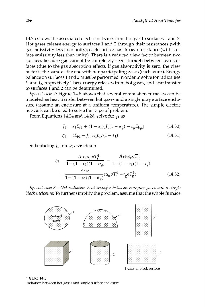
Special case 2: Figure 14.8 shows that several combustion furnaces can be
modeled as heat transfer between hot gases and a single gray surface enclosure (assume an enclosure at a uniform temperature). The simple electric
network can be used to solve this type of problem.
From Equations 14.24 and 14.28, solve for q 1 as
J 1 = ε 1 E b1 + (1 − ε 1 )[ J 1 (1 − α g ) + ε g E bg ]
(14.30)
q 1 = (E b1 − J 1 )A 1 ε 1 /(1 − ε 1 )
(14.31)
Substituting J 1 into q 1 , we obtain
A 1 ε 1 α g σT s
4
A 1 ε 1 ε g σT g
4
q 1 =
−
1− (1 − ε 1 )(1 − α g )
1− (1 − ε 1 )(1 − α g )
A 1 ε 1
=
(α g σT
4
−ε σT g
4 )
(14.32)
1− (1 − ε 1 )(1 − α g )
s
g
Special case 3—Net radiation heat transfer between nongray gases and a single
black enclosure: To further simplify the problem, assume that the whole furnace
1
1
1
1
1
Natural
gases
1
1-gray or black surface
FIGURE 14.8
Radiation between hot gases and single-surface enclosure.
Analytical Heat Transfer
14.7b shows the associated electric network from hot gas to surfaces 1 and 2.
Hot gases release energy to surfaces 1 and 2 through their resistances (with
gas emissivity less than unity); each surface has its own resistance (with surface emissivity less than unity). There is a reduced view factor between two
surfaces because gas cannot be completely seen through between two surfaces (due to the gas absorption effect). If gas absorptivity is zero, the view
factor is the same as the one with nonparticipating gases (such as air). Energy
balance on surfaces 1 and 2 must be performed in order to solve for radiosities
J 1 and J 2 , respectively. Then, energy releases from hot gases, and heat transfer
to surfaces 1 and 2 can be determined.
Special case 2: Figure 14.8 shows that several combustion furnaces can be
modeled as heat transfer between hot gases and a single gray surface enclosure (assume an enclosure at a uniform temperature). The simple electric
network can be used to solve this type of problem.
From Equations 14.24 and 14.28, solve for q 1 as
J 1 = ε 1 E b1 + (1 − ε 1 )[ J 1 (1 − α g ) + ε g E bg ]
(14.30)
q 1 = (E b1 − J 1 )A 1 ε 1 /(1 − ε 1 )
(14.31)
Substituting J 1 into q 1 , we obtain
A 1 ε 1 α g σT s
4
A 1 ε 1 ε g σT g
4
q 1 =
−
1− (1 − ε 1 )(1 − α g )
1− (1 − ε 1 )(1 − α g )
A 1 ε 1
=
(α g σT
4
−ε σT g
4 )
(14.32)
1− (1 − ε 1 )(1 − α g )
s
g
Special case 3—Net radiation heat transfer between nongray gases and a single
black enclosure: To further simplify the problem, assume that the whole furnace
1
1
1
1
1
Natural
gases
1
1-gray or black surface
FIGURE 14.8
Radiation between hot gases and single-surface enclosure.