

h 1
T ∞,1
T s,1
T s,2
, α
k
L
T ∞,2 h 2
x
0
Cold fluid
Hot fluid
T ∞,1
1
Ah 1
T s,1
L
Ak
T s,2
1
Ah 2
T ∞,2
q
q
14
Analytical Heat Transfer
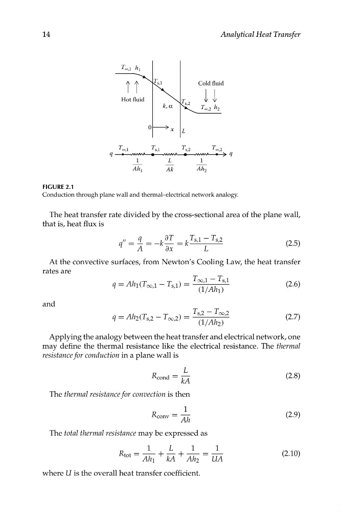
FIGURE 2.1
Conduction through plane wall and thermal–electrical network analogy.
The heat transfer rate divided by the cross-sectional area of the plane wall,
that is, heat flux is
""
q
∂T
T s,1 − T s,2
q =
= −k
= k
(2.5)
A
∂x
L
At the convective surfaces, from Newton’s Cooling Law, the heat transfer
rates are
T ∞,1 − T s,1
q = Ah 1 (T ∞,1 − T s,1 ) =
(2.6)
(1/Ah 1 )
and
T s,2 − T ∞,2
q = Ah 2 (T s,2 − T ∞,2 ) =
(2.7)
(1/Ah 2 )
Applying the analogy between the heat transfer and electrical network, one
may define the thermal resistance like the electrical resistance. The thermal
resistance for conduction in a plane wall is
L
R cond =
(2.8)
kA
The thermal resistance for convection is then
1
R conv =
(2.9)
Ah
The total thermal resistance may be expressed as
1
L
1
1
R tot =
+
+
=
(2.10)
Ah 1
kA Ah 2
UA
where U is the overall heat transfer coefficient.
T ∞,1
T s,1
T s,2
, α
k
L
T ∞,2 h 2
x
0
Cold fluid
Hot fluid
T ∞,1
1
Ah 1
T s,1
L
Ak
T s,2
1
Ah 2
T ∞,2
q
q
14
Analytical Heat Transfer
FIGURE 2.1
Conduction through plane wall and thermal–electrical network analogy.
The heat transfer rate divided by the cross-sectional area of the plane wall,
that is, heat flux is
""
q
∂T
T s,1 − T s,2
q =
= −k
= k
(2.5)
A
∂x
L
At the convective surfaces, from Newton’s Cooling Law, the heat transfer
rates are
T ∞,1 − T s,1
q = Ah 1 (T ∞,1 − T s,1 ) =
(2.6)
(1/Ah 1 )
and
T s,2 − T ∞,2
q = Ah 2 (T s,2 − T ∞,2 ) =
(2.7)
(1/Ah 2 )
Applying the analogy between the heat transfer and electrical network, one
may define the thermal resistance like the electrical resistance. The thermal
resistance for conduction in a plane wall is
L
R cond =
(2.8)
kA
The thermal resistance for convection is then
1
R conv =
(2.9)
Ah
The total thermal resistance may be expressed as
1
L
1
1
R tot =
+
+
=
(2.10)
Ah 1
kA Ah 2
UA
where U is the overall heat transfer coefficient.