

X f,h
V =
1 U max
2
U max
x
τ w πDΔx
Δx
PA c
(P + ΔP)A c
ρu · u · d A c
∫
ρu · u · dA c
∫
2πr dr
2πr dr
ΔP
Δx
f
0
Re D
172
Analytical Heat Transfer
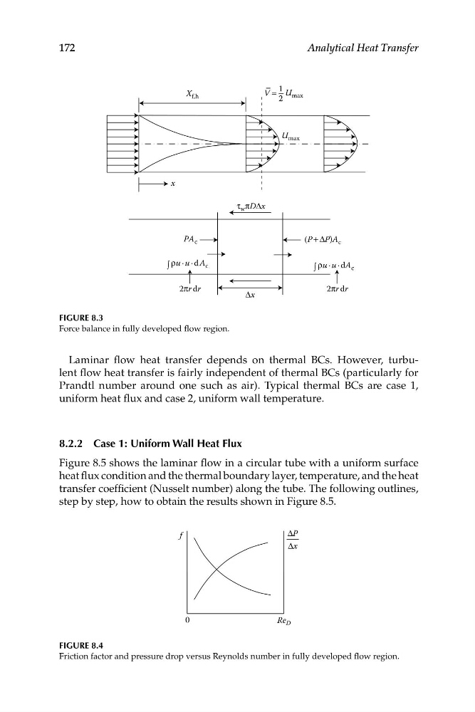
FIGURE 8.3
Force balance in fully developed flow region.
Laminar flow heat transfer depends on thermal BCs. However, turbulent flow heat transfer is fairly independent of thermal BCs (particularly for
Prandtl number around one such as air). Typical thermal BCs are case 1,
uniform heat flux and case 2, uniform wall temperature.
8.2.2 Case 1: Uniform Wall Heat Flux
Figure 8.5 shows the laminar flow in a circular tube with a uniform surface
heat flux condition and the thermal boundary layer, temperature, and the heat
transfer coefficient (Nusselt number) along the tube. The following outlines,
step by step, how to obtain the results shown in Figure 8.5.
FIGURE 8.4
Friction factor and pressure drop versus Reynolds number in fully developed flow region.
V =
1 U max
2
U max
x
τ w πDΔx
Δx
PA c
(P + ΔP)A c
ρu · u · d A c
∫
ρu · u · dA c
∫
2πr dr
2πr dr
ΔP
Δx
f
0
Re D
172
Analytical Heat Transfer
FIGURE 8.3
Force balance in fully developed flow region.
Laminar flow heat transfer depends on thermal BCs. However, turbulent flow heat transfer is fairly independent of thermal BCs (particularly for
Prandtl number around one such as air). Typical thermal BCs are case 1,
uniform heat flux and case 2, uniform wall temperature.
8.2.2 Case 1: Uniform Wall Heat Flux
Figure 8.5 shows the laminar flow in a circular tube with a uniform surface
heat flux condition and the thermal boundary layer, temperature, and the heat
transfer coefficient (Nusselt number) along the tube. The following outlines,
step by step, how to obtain the results shown in Figure 8.5.
FIGURE 8.4
Friction factor and pressure drop versus Reynolds number in fully developed flow region.