

288
Electromagnetic Fields in Biological Systems
dipole’s axis, with the exception of the feeding gap (Bernardi, Cavagnaro, and Pisa 1996;
Martens et al. 1995). The second is the “thin” model in which a static approximation
is applied and the electric and magnetic field components are assumed to vary as 1/r
near the wire, where r is the distance from the wire center (Lazzi, Gandhi, and Sullivan
2000). The third is the “thick wire” approximation, obtained by assigning the copper
conductivity value to each cell belonging to the dipole, with the exception of the antenna
feed-point (Chen and Wang 1994).
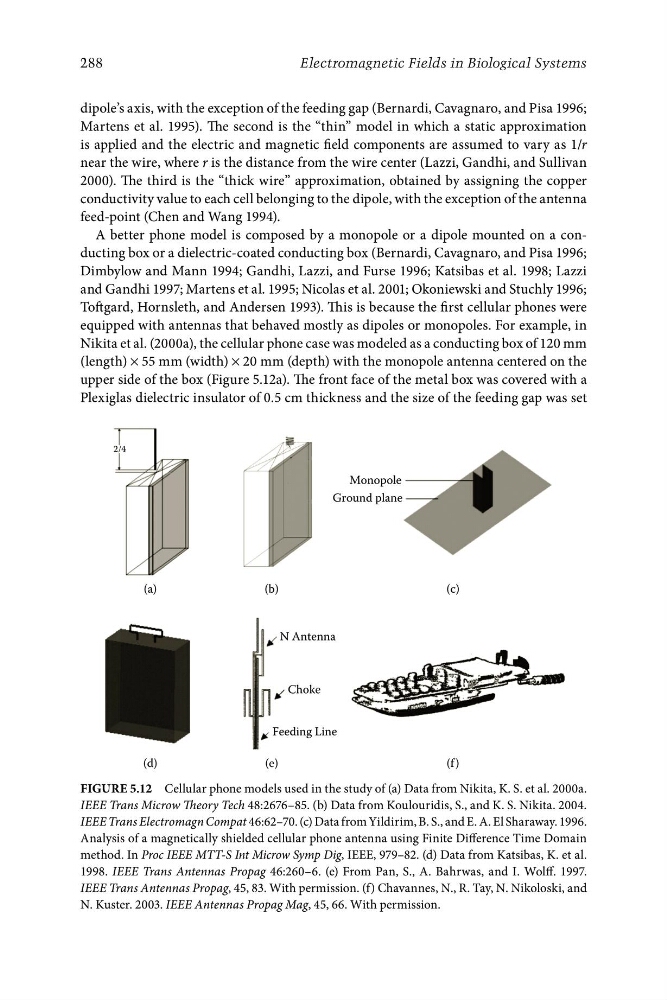
A better phone model is composed by a monopole or a dipole mounted on a conducting box or a dielectric-coated conducting box (Bernardi, Cavagnaro, and Pisa 1996;
Dimbylow and Mann 1994; Gandhi, Lazzi, and Furse 1996; Katsibas et al. 1998; Lazzi
and Gandhi 1997; Martens et al. 1995; Nicolas et al. 2001; Okoniewski and Stuchly 1996;
Toftgard, Hornsleth, and Andersen 1993). This is because the first cellular phones were
equipped with antennas that behaved mostly as dipoles or monopoles. For example, in
Nikita et al. (2000a), the cellular phone case was modeled as a conducting box of 120 mm
(length) × 55 mm (width) × 20 mm (depth) with the monopole antenna centered on the
upper side of the box (Figure 5.12a). The front face of the metal box was covered with a
Plexiglas dielectric insulator of 0.5 cm thickness and the size of the feeding gap was set
2/4
Monopole
Ground plane
(a)
(b)
(c)
N Antenna
Choke
Feeding Line
(d)
(e)
(f )
Figure 5.12 Cellular phone models used in the study of (a) Data from Nikita, K. S. et al. 2000a.
IEEE Trans Microw Theory Tech 48:2676–85. (b) Data from Koulouridis, S., and K. S. Nikita. 2004.
IEEE Trans Electromagn Compat 46:62–70. (c) Data from Yildirim, B. S., and E. A. El Sharaway. 1996.
Analysis of a magnetically shielded cellular phone antenna using Finite Difference Time Domain
method. In Proc IEEE MTT-S Int Microw Symp Dig, IEEE, 979–82. (d) Data from Katsibas, K. et al.
1998. IEEE Trans Antennas Propag 46:260–6. (e) From Pan, S., A. Bahrwas, and I. Wolff. 1997.
IEEE Trans Antennas Propag, 45, 83. With permission. (f) Chavannes, N., R. Tay, N. Nikoloski, and
N. Kuster. 2003. IEEE Antennas Propag Mag, 45, 66. With permission.
Electromagnetic Fields in Biological Systems
dipole’s axis, with the exception of the feeding gap (Bernardi, Cavagnaro, and Pisa 1996;
Martens et al. 1995). The second is the “thin” model in which a static approximation
is applied and the electric and magnetic field components are assumed to vary as 1/r
near the wire, where r is the distance from the wire center (Lazzi, Gandhi, and Sullivan
2000). The third is the “thick wire” approximation, obtained by assigning the copper
conductivity value to each cell belonging to the dipole, with the exception of the antenna
feed-point (Chen and Wang 1994).
A better phone model is composed by a monopole or a dipole mounted on a conducting box or a dielectric-coated conducting box (Bernardi, Cavagnaro, and Pisa 1996;
Dimbylow and Mann 1994; Gandhi, Lazzi, and Furse 1996; Katsibas et al. 1998; Lazzi
and Gandhi 1997; Martens et al. 1995; Nicolas et al. 2001; Okoniewski and Stuchly 1996;
Toftgard, Hornsleth, and Andersen 1993). This is because the first cellular phones were
equipped with antennas that behaved mostly as dipoles or monopoles. For example, in
Nikita et al. (2000a), the cellular phone case was modeled as a conducting box of 120 mm
(length) × 55 mm (width) × 20 mm (depth) with the monopole antenna centered on the
upper side of the box (Figure 5.12a). The front face of the metal box was covered with a
Plexiglas dielectric insulator of 0.5 cm thickness and the size of the feeding gap was set
2/4
Monopole
Ground plane
(a)
(b)
(c)
N Antenna
Choke
Feeding Line
(d)
(e)
(f )
Figure 5.12 Cellular phone models used in the study of (a) Data from Nikita, K. S. et al. 2000a.
IEEE Trans Microw Theory Tech 48:2676–85. (b) Data from Koulouridis, S., and K. S. Nikita. 2004.
IEEE Trans Electromagn Compat 46:62–70. (c) Data from Yildirim, B. S., and E. A. El Sharaway. 1996.
Analysis of a magnetically shielded cellular phone antenna using Finite Difference Time Domain
method. In Proc IEEE MTT-S Int Microw Symp Dig, IEEE, 979–82. (d) Data from Katsibas, K. et al.
1998. IEEE Trans Antennas Propag 46:260–6. (e) From Pan, S., A. Bahrwas, and I. Wolff. 1997.
IEEE Trans Antennas Propag, 45, 83. With permission. (f) Chavannes, N., R. Tay, N. Nikoloski, and
N. Kuster. 2003. IEEE Antennas Propag Mag, 45, 66. With permission.