

64
5 How to Conduct an Experiment in the Field …
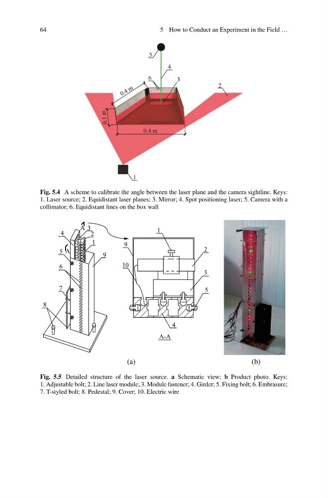
Fig. 5.4 A scheme to calibrate the angle between the laser plane and the camera sightline. Keys:
1. Laser source; 2. Equidistant laser planes; 3. Mirror; 4. Spot positioning laser; 5. Camera with a
collimator; 6. Equidistant lines on the box wall
A
A
A-A
1
1
2
3
4
5
6
7
8
9
9
10
4
5
3
2
(a)
(b)
Fig. 5.5 Detailed structure of the laser source. a Schematic view; b Product photo. Keys:
1. Adjustable bolt; 2. Line laser module; 3. Module fastener; 4. Girder; 5. Fixing bolt; 6. Embrasure;
7. T-styled bolt; 8. Pedestal; 9. Cover; 10. Electric wire
5 How to Conduct an Experiment in the Field …
Fig. 5.4 A scheme to calibrate the angle between the laser plane and the camera sightline. Keys:
1. Laser source; 2. Equidistant laser planes; 3. Mirror; 4. Spot positioning laser; 5. Camera with a
collimator; 6. Equidistant lines on the box wall
A
A
A-A
1
1
2
3
4
5
6
7
8
9
9
10
4
5
3
2
(a)
(b)
Fig. 5.5 Detailed structure of the laser source. a Schematic view; b Product photo. Keys:
1. Adjustable bolt; 2. Line laser module; 3. Module fastener; 4. Girder; 5. Fixing bolt; 6. Embrasure;
7. T-styled bolt; 8. Pedestal; 9. Cover; 10. Electric wire