

While polymers in composites are usually aligned to improve their mechanical
performance, conjugated polymers are aligned to improve their optoelectronic
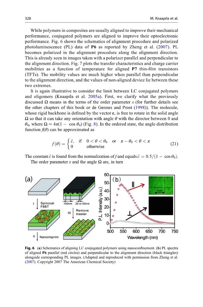
performance. Fig. 6 shows the schematics of alignment procedure and polarized
photoluminescence (PL) data of P6 as reported by Zheng et al. (2007). PL
becomes polarized in the alignment procedure along the alignment direction.
This is already seen in images taken with a polarizer parallel and perpendicular to
the alignment direction. Fig. 7 plots the transfer characteristics and charge carrier
mobilities as a function of temperature for aligned P7 thin-film transistors
(TFTs). The mobility values are much higher when parallel than perpendicular
to the alignment direction, and the values of non-aligned device lie between these
two extremes.
It is again illustrative to consider the limit between LC conjugated polymers
and oligomers (Knaapila et al. 2005a). First, we clarify what the previously
discussed Ω means in the terms of the order parameter s (for further details see
the other chapters of this book or de Gennes and Prost (1998)). The molecule,
whose rigid backbone is defined by the vector c, is free to rotate in the solid angle
Ω so that it can take any orientation with angle θ with the director between 0 and
θ 0 , where Ω = 4π(1 À cos θ 0 ) (Fig. 8). In the ordered state, the angle distribution
function f(θ) can be approximated as
f θ
ð Þ ¼
~
c, if 0 < θ < θ 0 or π À θ 0 < θ < π
0
otherwise
&
(21)
The constant ~
c is found from the normalization of f and equals ~
c ¼ 0:5= 1 À cos θ 0
ð
Þ .
The order parameter s and the angle Ω are, in turn
Fig. 6 (a) Schematics of aligning LC conjugated polymers using nanoconfinement. (b) PL spectra
of aligned P6 parallel (red circles) and perpendicular to the alignment direction (black triangles)
alongside corresponding PL images. (Adapted and reproduced with permission from Zheng et al.
(2007). Copyright 2007 The American Chemical Society)
328
M. Knaapila et al.
performance, conjugated polymers are aligned to improve their optoelectronic
performance. Fig. 6 shows the schematics of alignment procedure and polarized
photoluminescence (PL) data of P6 as reported by Zheng et al. (2007). PL
becomes polarized in the alignment procedure along the alignment direction.
This is already seen in images taken with a polarizer parallel and perpendicular to
the alignment direction. Fig. 7 plots the transfer characteristics and charge carrier
mobilities as a function of temperature for aligned P7 thin-film transistors
(TFTs). The mobility values are much higher when parallel than perpendicular
to the alignment direction, and the values of non-aligned device lie between these
two extremes.
It is again illustrative to consider the limit between LC conjugated polymers
and oligomers (Knaapila et al. 2005a). First, we clarify what the previously
discussed Ω means in the terms of the order parameter s (for further details see
the other chapters of this book or de Gennes and Prost (1998)). The molecule,
whose rigid backbone is defined by the vector c, is free to rotate in the solid angle
Ω so that it can take any orientation with angle θ with the director between 0 and
θ 0 , where Ω = 4π(1 À cos θ 0 ) (Fig. 8). In the ordered state, the angle distribution
function f(θ) can be approximated as
f θ
ð Þ ¼
~
c, if 0 < θ < θ 0 or π À θ 0 < θ < π
0
otherwise
&
(21)
The constant ~
c is found from the normalization of f and equals ~
c ¼ 0:5= 1 À cos θ 0
ð
Þ .
The order parameter s and the angle Ω are, in turn
Fig. 6 (a) Schematics of aligning LC conjugated polymers using nanoconfinement. (b) PL spectra
of aligned P6 parallel (red circles) and perpendicular to the alignment direction (black triangles)
alongside corresponding PL images. (Adapted and reproduced with permission from Zheng et al.
(2007). Copyright 2007 The American Chemical Society)
328
M. Knaapila et al.