

4. In-plane viscous-driven steady state (IV): In this plane mode, the director profile
shows a flow-aligning bulk region and two boundary layers. On traversing the
boundary, the director rotates form the aligning angle to the flow direction at the
walls
5. Out-of-plane elastic-driven steady state with achiral structure (OEA): In this
nonplanar mode, the director shows steady twist structures, and the twist angle
profiles are symmetric with respect to the centerline. The steady state arises due to
the long-range order elasticity. Similar solutions are presented by the LeslieEricksen solutions. Following from the bottom to top bounding surface, the net
director twist rotation is null
6. Out-of-plane elastic-driven steady state with chiral structure (OEC[n]): In this
nonplanar mode, the director shows steady twist structure, with nπ (n = 1, 2)
radian difference between the anchoring angles at the lower and upper bounding
surfaces, but without the presence of defects or disclinations. The different
anchoring conditions are smoothly connected by the chiral director structure. A
similar OEC solutions is predicted by the LE equations
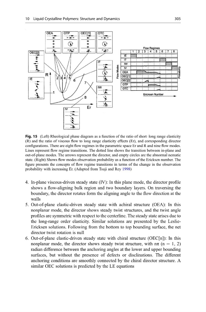
Fig. 15 (Left) Rheological phase diagram as a function of the ratio of short–long range elasticity
(R) and the ratio of viscous flow to long range elasticity effects (Er), and corresponding director
configurations. There are eight flow regimes in the parametric space Er and R and nine flow modes.
Lines represent flow regime transitions. The dotted line shows the transition between in-plane and
out-of-plane modes. The arrows represent the director, and empty circles are the abnormal nematic
state. (Right) Shows flow modes observation probability as a function of the Ericksen number. The
figure presents the concepts of flow regime transitions in terms of the change in the observation
probability with increasing Er. (Adapted from Tsuji and Rey 1998)
10 Liquid Crystalline Polymers: Structure and Dynamics
305
shows a flow-aligning bulk region and two boundary layers. On traversing the
boundary, the director rotates form the aligning angle to the flow direction at the
walls
5. Out-of-plane elastic-driven steady state with achiral structure (OEA): In this
nonplanar mode, the director shows steady twist structures, and the twist angle
profiles are symmetric with respect to the centerline. The steady state arises due to
the long-range order elasticity. Similar solutions are presented by the LeslieEricksen solutions. Following from the bottom to top bounding surface, the net
director twist rotation is null
6. Out-of-plane elastic-driven steady state with chiral structure (OEC[n]): In this
nonplanar mode, the director shows steady twist structure, with nπ (n = 1, 2)
radian difference between the anchoring angles at the lower and upper bounding
surfaces, but without the presence of defects or disclinations. The different
anchoring conditions are smoothly connected by the chiral director structure. A
similar OEC solutions is predicted by the LE equations
Fig. 15 (Left) Rheological phase diagram as a function of the ratio of short–long range elasticity
(R) and the ratio of viscous flow to long range elasticity effects (Er), and corresponding director
configurations. There are eight flow regimes in the parametric space Er and R and nine flow modes.
Lines represent flow regime transitions. The dotted line shows the transition between in-plane and
out-of-plane modes. The arrows represent the director, and empty circles are the abnormal nematic
state. (Right) Shows flow modes observation probability as a function of the Ericksen number. The
figure presents the concepts of flow regime transitions in terms of the change in the observation
probability with increasing Er. (Adapted from Tsuji and Rey 1998)
10 Liquid Crystalline Polymers: Structure and Dynamics
305