

87
4
5 Pressure Difference—This could be understood with a model
flow through a circular pipe as
∆P P P
= −
1
2
(4.19)
where P 1 is high pressure and P 2 is low pressure.
The pressure gradient is given as
Pressure gradient =
∆P
l
(4.20)
where l is the length of the pipe.
The velocity profile of a fluid flowing through a pipe may be
parabolic, a straight line, concave headed, etc., depending upon
the polymer. If water is flowing through a pipe, the velocity profile
is parabolic. For the flow in pipe, the volumetric or mass flow rate,
Q, is
Q
R
=
×
(
)
∫
0
Local area Local velocity
(4.21)
where R is the radius of the pipe.
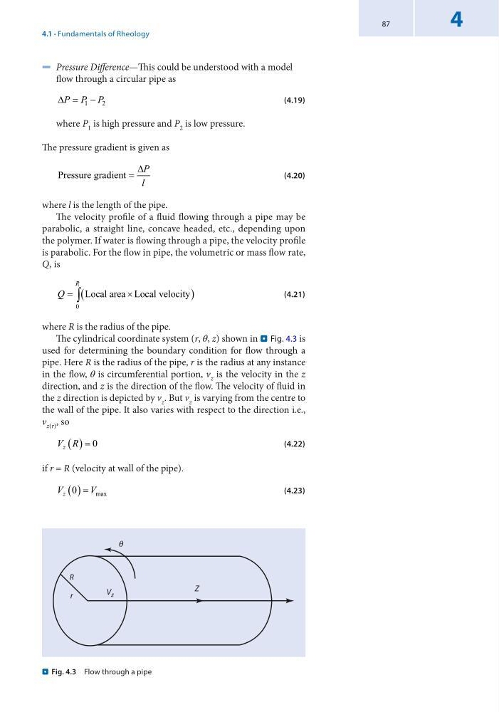
The cylindrical coordinate system (r, θ, z) shown in . Fig. 4.3 is
used for determining the boundary condition for flow through a
pipe. Here R is the radius of the pipe, r is the radius at any instance
in the flow, θ is circumferential portion, v z is the velocity in the z
direction, and z is the direction of the flow. The velocity of fluid in
the z direction is depicted by v z . But v z is varying from the centre to
the wall of the pipe. It also varies with respect to the direction i.e.,
v z(r) , so
V R
z ( ) = 0
(4.22)
if r = R (velocity at wall of the pipe).
V
V
z 0
( ) = max
(4.23)
Z
R
q
V z
r
. Fig. 4.3 Flow through a pipe
4.1 · Fundamentals of Rheology
4
5 Pressure Difference—This could be understood with a model
flow through a circular pipe as
∆P P P
= −
1
2
(4.19)
where P 1 is high pressure and P 2 is low pressure.
The pressure gradient is given as
Pressure gradient =
∆P
l
(4.20)
where l is the length of the pipe.
The velocity profile of a fluid flowing through a pipe may be
parabolic, a straight line, concave headed, etc., depending upon
the polymer. If water is flowing through a pipe, the velocity profile
is parabolic. For the flow in pipe, the volumetric or mass flow rate,
Q, is
Q
R
=
×
(
)
∫
0
Local area Local velocity
(4.21)
where R is the radius of the pipe.
The cylindrical coordinate system (r, θ, z) shown in . Fig. 4.3 is
used for determining the boundary condition for flow through a
pipe. Here R is the radius of the pipe, r is the radius at any instance
in the flow, θ is circumferential portion, v z is the velocity in the z
direction, and z is the direction of the flow. The velocity of fluid in
the z direction is depicted by v z . But v z is varying from the centre to
the wall of the pipe. It also varies with respect to the direction i.e.,
v z(r) , so
V R
z ( ) = 0
(4.22)
if r = R (velocity at wall of the pipe).
V
V
z 0
( ) = max
(4.23)
Z
R
q
V z
r
. Fig. 4.3 Flow through a pipe
4.1 · Fundamentals of Rheology