

Topics in Current Chemistry (2019) 377:22
1 3
Once the e
a (x) profile has been obtained, the average LVRPA in the reactor volume
can be calculated as ⟨e a (x)⟩ V R =
1
L R
∫
x=L R
x=0
e a (x)dx (expression valid for one-dimensional radiation models). The values of ⟨e
a (x)⟩ V R enable one to analyze the effect of the
catalyst concentration on the total radiation absorption and, consequently, to obtain an
optimal catalyst concentration from the perspective of radiation absorption. Figure 14
shows the computed values of the average LVRPA for Aeroxide TiO 2 P 25 as a function of catalyst concentration.
As shown in the figure, at a TiO 2 concentration of 0.5 g L
−1
, radiation absorption in
the reactor reaches some form of saturation, and subsequent increases in catalyst concentration do not produce a significant increase in total radiation absorption.
4.2 Pollutant Degradation Results
This section provides an illustrative example of the kinetic study of the photocatalytic degradation of a pharmaceutical product, clofibric acid (CA) [8]. The
formation and subsequent degradation of the primary organic intermediates of
the reaction, 4-chlorophenol (4-CP) and benzoquinone (BQ), was also analyzed
in the study. The photocatalytic reaction was carried out in a cylindrical glass
reactor with two flat windows built with borosilicate ground glass. The experimental system was composed of a halogenated mercury lamp at the focal axis
of a parabolic reflector as a source of radiation, a storage tank equipped with a
water-circulating jacket to ensure isothermal conditions, and a peristaltic pump to
operate the system in batch recirculation and good mixing.
According to the reaction pathway for the CA degradation [89], the following
was proposed: (i) formation of the reaction intermediates 4-CP and BQ from CA,
(ii) formation of more BQ from 4-CP, and (iii) degradation of 4-CP and BQ to
form organic compounds of low molecular weight and, eventually, CO 2 , H 2 O and
HCl. Hence, the mass balances and initial conditions for CA, 4-CP, and BQ in
this well-mixed reactor are:
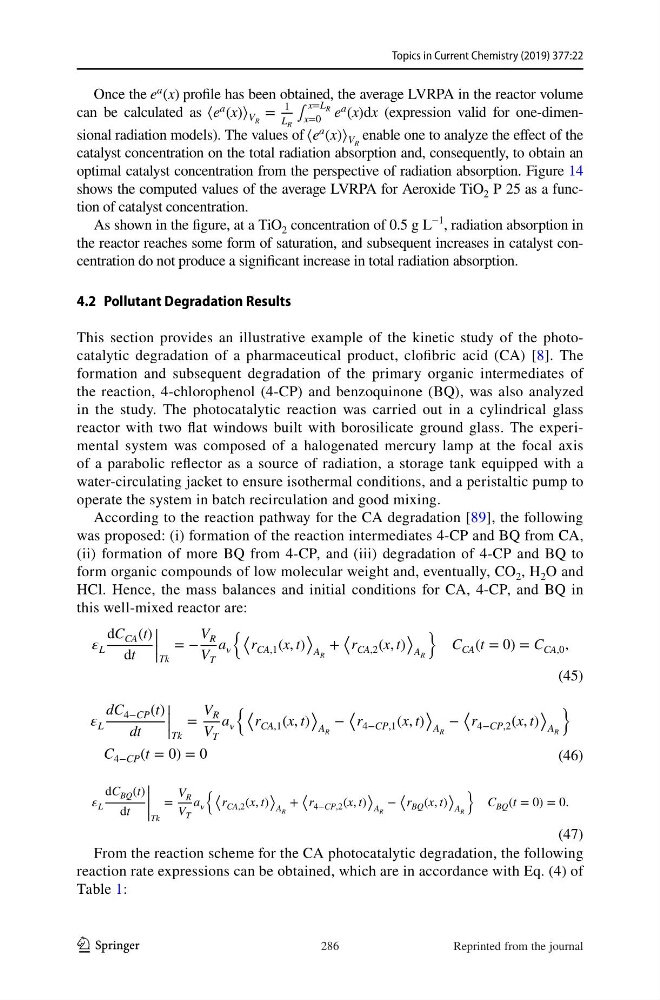
From the reaction scheme for the CA photocatalytic degradation, the following
reaction rate expressions can be obtained, which are in accordance with Eq. (4) of
Table 1:
(45)
L
dC CA (t)
dt
|
|
|
|Tk
= −
V R
V T
a
⟨
r CA,1 (x, t)
⟩
A R
+
⟨
r CA,2 (x, t)
⟩
A R
C CA (t = 0) = C CA,0 ,
(46)
L
dC 4−CP (t)
dt
|
|
|
|Tk
=
V R
V T
a
⟨
r CA,1 (x, t)
⟩
A R
−
⟨
r 4−CP,1 (x, t)
⟩
A R
−
⟨
r 4−CP,2 (x, t)
⟩
A R
C 4−CP (t = 0) = 0
(47)
L
dC BQ (t)
dt
|
|
|
|
|Tk
=
V R
V T
a
⟨
r CA,2 (x, t)
⟩
A R
+
⟨
r 4−CP,2 (x, t)
⟩
A R
−
⟨
r BQ (x, t)
⟩
A R
C BQ (t = 0) = 0.
286
Reprinted from the journal
1 3
Once the e
a (x) profile has been obtained, the average LVRPA in the reactor volume
can be calculated as ⟨e a (x)⟩ V R =
1
L R
∫
x=L R
x=0
e a (x)dx (expression valid for one-dimensional radiation models). The values of ⟨e
a (x)⟩ V R enable one to analyze the effect of the
catalyst concentration on the total radiation absorption and, consequently, to obtain an
optimal catalyst concentration from the perspective of radiation absorption. Figure 14
shows the computed values of the average LVRPA for Aeroxide TiO 2 P 25 as a function of catalyst concentration.
As shown in the figure, at a TiO 2 concentration of 0.5 g L
−1
, radiation absorption in
the reactor reaches some form of saturation, and subsequent increases in catalyst concentration do not produce a significant increase in total radiation absorption.
4.2 Pollutant Degradation Results
This section provides an illustrative example of the kinetic study of the photocatalytic degradation of a pharmaceutical product, clofibric acid (CA) [8]. The
formation and subsequent degradation of the primary organic intermediates of
the reaction, 4-chlorophenol (4-CP) and benzoquinone (BQ), was also analyzed
in the study. The photocatalytic reaction was carried out in a cylindrical glass
reactor with two flat windows built with borosilicate ground glass. The experimental system was composed of a halogenated mercury lamp at the focal axis
of a parabolic reflector as a source of radiation, a storage tank equipped with a
water-circulating jacket to ensure isothermal conditions, and a peristaltic pump to
operate the system in batch recirculation and good mixing.
According to the reaction pathway for the CA degradation [89], the following
was proposed: (i) formation of the reaction intermediates 4-CP and BQ from CA,
(ii) formation of more BQ from 4-CP, and (iii) degradation of 4-CP and BQ to
form organic compounds of low molecular weight and, eventually, CO 2 , H 2 O and
HCl. Hence, the mass balances and initial conditions for CA, 4-CP, and BQ in
this well-mixed reactor are:
From the reaction scheme for the CA photocatalytic degradation, the following
reaction rate expressions can be obtained, which are in accordance with Eq. (4) of
Table 1:
(45)
L
dC CA (t)
dt
|
|
|
|Tk
= −
V R
V T
a
⟨
r CA,1 (x, t)
⟩
A R
+
⟨
r CA,2 (x, t)
⟩
A R
C CA (t = 0) = C CA,0 ,
(46)
L
dC 4−CP (t)
dt
|
|
|
|Tk
=
V R
V T
a
⟨
r CA,1 (x, t)
⟩
A R
−
⟨
r 4−CP,1 (x, t)
⟩
A R
−
⟨
r 4−CP,2 (x, t)
⟩
A R
C 4−CP (t = 0) = 0
(47)
L
dC BQ (t)
dt
|
|
|
|
|Tk
=
V R
V T
a
⟨
r CA,2 (x, t)
⟩
A R
+
⟨
r 4−CP,2 (x, t)
⟩
A R
−
⟨
r BQ (x, t)
⟩
A R
C BQ (t = 0) = 0.
286
Reprinted from the journal