

Topics in Current Chemistry (2018) 376:42
1 3
than compressed hydrogen gas (5.6 MJ l
−1
) or 28 wt% NH 4 OH (1.17 MJ l
−1
); (2)
urea sources are abundant from animals’ urine (contents ca. 2–2.5 wt%). Compared
with conventional H 2 , direct utilization of wastewater rich in urea as fuels is more
efficient for power generation; (3) the storage and transportation of urea are more
convenient than hydrogen gas for its non-toxic and incombustible features; (4) the
oxidative reaction products of urea are safely stable carbonate and nitrogen. On the
other hand, Serban et al. employed Ni/MWCNTs–Pt/C as twin electrodes to form
direct urea/H 2 O 2 fuel cell (DUPFC) that performed a maximum power density of
0.05 mW cm
−2
with the OCV of 0.25 V. Then it caught the researchers’ attention
to focus on the cathodic oxidant of DUFCs and choose liquid hydrogen peroxide
(H 2 O 2 ) as the oxidants for their priorities. In certain DUPFC, the anodic electrooxidation of urea occurs in a basic media, while the cathodic electro-reduction of
H 2 O 2 can react both in basic and acidic media [52, 53]. A specific type of acidic fuel
cell in Cao et al.’s [54] work that used H 2 O 2 as cathodic oxidant and Pd/CFC as the
cathodic catalyst increased the OCV to ~ 0.8 V and the power density reached ~ 5
mW cm
−2
. The cell performance was much higher than that used oxygen as oxidant
(0.65 V, 1.5 mW cm
−2
). This was probably ascribed to the fact that H 2 O 2 used as
oxidants of DUFCs can enhance theoretical OCV of the cell to 2.51 V, much better
than O 2 as oxidant (for basic media: OCV = 1.15 V) [55].
According to the differences of cathodic oxidant and media, DUFCs can be
roughly divided into three of the most common and practical types: oxygen reduction reaction in basic media, hydrogen peroxide electro-reduction reaction in basic
media, and hydrogen peroxide electro-reduction reaction in acidic media. Both of
the fuel cell systems utilize cation exchange membrane (CEM) as separator. When
the electrons flow from anode to cathode throughout external circuit, then K
+
flows
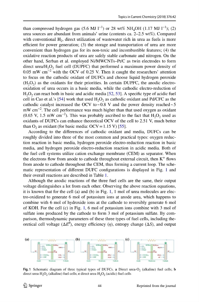
from anode to cathode throughout the CEM, thus forming a current loop. The schematic representation of different DUFC configurations is displayed in Fig. 1 and
their overall reactions are described in Table 1.
Although the anodic reactions of the three fuel cells are the same, their output
voltage distinguishes a lot from each other. Observing the above reaction equations,
it is known that for the cell (a) and (b) in Fig. 1, 1 mol of urea molecules are electro-oxidized to generate 6 mol of potassium ions at anode area, which happens to
combine with 6 mol of hydroxide ions at the cathode to reversibly generate 6 mol
of KOH. For the cell (c) in Fig. 1, 6 mol of potassium ions combine with 3 mol of
sulfate ions produced by the cathode to form 3 mol of potassium sulfate. By comparison, thermodynamic parameters of these three types of fuel cells, including theoretical cell voltage (ΔE
θ
), energy efficiency (η), entropy change (ΔS), and output
Fig. 1 Schematic diagram of three typical types of DUFCs. a Direct urea-O 2 (alkaline) fuel cells; b
direct urea-H 2 O 2 (alkaline) fuel cells; c direct urea-H 2 O 2 (acidic) fuel cells
Reprinted from the journal
44
1 3
than compressed hydrogen gas (5.6 MJ l
−1
) or 28 wt% NH 4 OH (1.17 MJ l
−1
); (2)
urea sources are abundant from animals’ urine (contents ca. 2–2.5 wt%). Compared
with conventional H 2 , direct utilization of wastewater rich in urea as fuels is more
efficient for power generation; (3) the storage and transportation of urea are more
convenient than hydrogen gas for its non-toxic and incombustible features; (4) the
oxidative reaction products of urea are safely stable carbonate and nitrogen. On the
other hand, Serban et al. employed Ni/MWCNTs–Pt/C as twin electrodes to form
direct urea/H 2 O 2 fuel cell (DUPFC) that performed a maximum power density of
0.05 mW cm
−2
with the OCV of 0.25 V. Then it caught the researchers’ attention
to focus on the cathodic oxidant of DUFCs and choose liquid hydrogen peroxide
(H 2 O 2 ) as the oxidants for their priorities. In certain DUPFC, the anodic electrooxidation of urea occurs in a basic media, while the cathodic electro-reduction of
H 2 O 2 can react both in basic and acidic media [52, 53]. A specific type of acidic fuel
cell in Cao et al.’s [54] work that used H 2 O 2 as cathodic oxidant and Pd/CFC as the
cathodic catalyst increased the OCV to ~ 0.8 V and the power density reached ~ 5
mW cm
−2
. The cell performance was much higher than that used oxygen as oxidant
(0.65 V, 1.5 mW cm
−2
). This was probably ascribed to the fact that H 2 O 2 used as
oxidants of DUFCs can enhance theoretical OCV of the cell to 2.51 V, much better
than O 2 as oxidant (for basic media: OCV = 1.15 V) [55].
According to the differences of cathodic oxidant and media, DUFCs can be
roughly divided into three of the most common and practical types: oxygen reduction reaction in basic media, hydrogen peroxide electro-reduction reaction in basic
media, and hydrogen peroxide electro-reduction reaction in acidic media. Both of
the fuel cell systems utilize cation exchange membrane (CEM) as separator. When
the electrons flow from anode to cathode throughout external circuit, then K
+
flows
from anode to cathode throughout the CEM, thus forming a current loop. The schematic representation of different DUFC configurations is displayed in Fig. 1 and
their overall reactions are described in Table 1.
Although the anodic reactions of the three fuel cells are the same, their output
voltage distinguishes a lot from each other. Observing the above reaction equations,
it is known that for the cell (a) and (b) in Fig. 1, 1 mol of urea molecules are electro-oxidized to generate 6 mol of potassium ions at anode area, which happens to
combine with 6 mol of hydroxide ions at the cathode to reversibly generate 6 mol
of KOH. For the cell (c) in Fig. 1, 6 mol of potassium ions combine with 3 mol of
sulfate ions produced by the cathode to form 3 mol of potassium sulfate. By comparison, thermodynamic parameters of these three types of fuel cells, including theoretical cell voltage (ΔE
θ
), energy efficiency (η), entropy change (ΔS), and output
Fig. 1 Schematic diagram of three typical types of DUFCs. a Direct urea-O 2 (alkaline) fuel cells; b
direct urea-H 2 O 2 (alkaline) fuel cells; c direct urea-H 2 O 2 (acidic) fuel cells
Reprinted from the journal
44