

80
I. E. Ivanov et al.
Fig. 6.3 Grid representation
Table 6.3 Boundary
conditions
Name
P (Pa)
Total temperature (K)
In
709,275 (7 atm)
300
out_space
50
–
out_strim
10
–
6.4.3 Boundary Conditions
For the expansion of the jet to be sufficient for condensation to form, the region in
the vacuum chamber behind the nozzle must have very low pressure. The formation
of clusters of the required size and their separation occurs in the inner region of the
skimmer, where an even higher vacuum is created than in a vacuum chamber. For
all boundaries of external areas (out_space), it is assumed that the total pressure on
them is the same. The flow parameters at the input and output boundaries are given
in Table 6.3.
6.4.4 Calculation Results
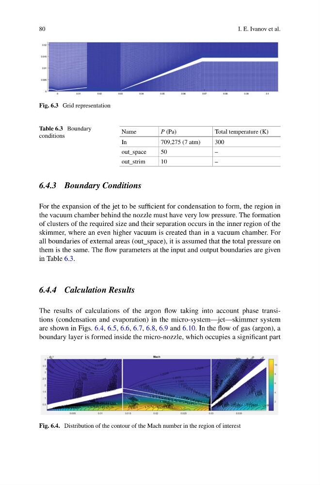
The results of calculations of the argon flow taking into account phase transitions (condensation and evaporation) in the micro-system—jet—skimmer system
are shown in Figs. 6.4, 6.5, 6.6, 6.7, 6.8, 6.9 and 6.10. In the flow of gas (argon), a
boundary layer is formed inside the micro-nozzle, which occupies a significant part
Fig. 6.4. Distribution of the contour of the Mach number in the region of interest
I. E. Ivanov et al.
Fig. 6.3 Grid representation
Table 6.3 Boundary
conditions
Name
P (Pa)
Total temperature (K)
In
709,275 (7 atm)
300
out_space
50
–
out_strim
10
–
6.4.3 Boundary Conditions
For the expansion of the jet to be sufficient for condensation to form, the region in
the vacuum chamber behind the nozzle must have very low pressure. The formation
of clusters of the required size and their separation occurs in the inner region of the
skimmer, where an even higher vacuum is created than in a vacuum chamber. For
all boundaries of external areas (out_space), it is assumed that the total pressure on
them is the same. The flow parameters at the input and output boundaries are given
in Table 6.3.
6.4.4 Calculation Results
The results of calculations of the argon flow taking into account phase transitions (condensation and evaporation) in the micro-system—jet—skimmer system
are shown in Figs. 6.4, 6.5, 6.6, 6.7, 6.8, 6.9 and 6.10. In the flow of gas (argon), a
boundary layer is formed inside the micro-nozzle, which occupies a significant part
Fig. 6.4. Distribution of the contour of the Mach number in the region of interest