

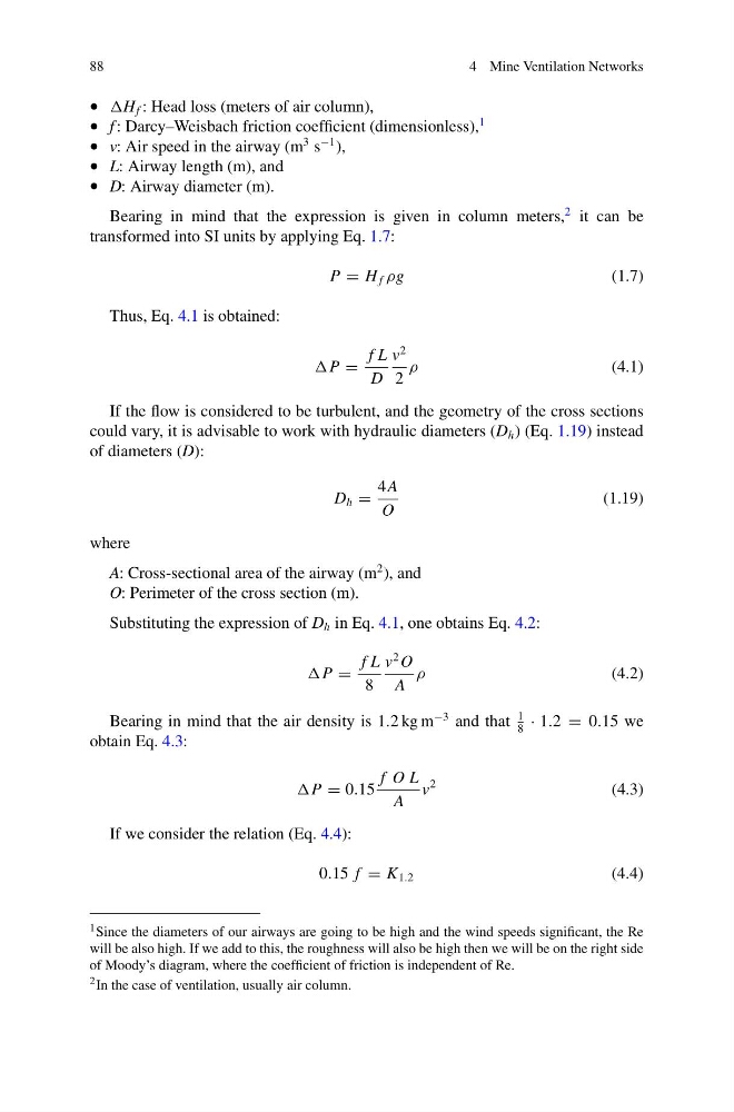
88
4 Mine Ventilation Networks
• H f : Head loss (meters of air column),
• f : Darcy–Weisbach friction coefficient (dimensionless),
1
• v: Air speed in the airway (m
3 s
−1 ),
• L: Airway length (m), and
• D: Airway diameter (m).
Bearing in mind that the expression is given in column meters,
2 it can be
transformed into SI units by applying Eq. 1.7:
P = H f ρg
(1.7)
Thus, Eq. 4.1 is obtained:
P =
f L
D
v
2
2
ρ
(4.1)
If the flow is considered to be turbulent, and the geometry of the cross sections
could vary, it is advisable to work with hydraulic diameters (D h ) (Eq. 1.19) instead
of diameters (D):
D h =
4 A
O
(1.19)
where
A: Cross-sectional area of the airway (m
2 ), and
O: Perimeter of the cross section (m).
Substituting the expression of D h in Eq. 4.1, one obtains Eq. 4.2:
P =
f L
8
v
2 O
A
ρ
(4.2)
Bearing in mind that the air density is 1.2 kg m
−3 and that
1
8
· 1.2 = 0.15 we
obtain Eq. 4.3:
P = 0.15
f O L
A
v
2
(4.3)
If we consider the relation (Eq. 4.4):
0.15 f = K 1.2
(4.4)
1 Since the diameters of our airways are going to be high and the wind speeds significant, the Re
will be also high. If we add to this, the roughness will also be high then we will be on the right side
of Moody’s diagram, where the coefficient of friction is independent of Re.
2 In the case of ventilation, usually air column.
4 Mine Ventilation Networks
• H f : Head loss (meters of air column),
• f : Darcy–Weisbach friction coefficient (dimensionless),
1
• v: Air speed in the airway (m
3 s
−1 ),
• L: Airway length (m), and
• D: Airway diameter (m).
Bearing in mind that the expression is given in column meters,
2 it can be
transformed into SI units by applying Eq. 1.7:
P = H f ρg
(1.7)
Thus, Eq. 4.1 is obtained:
P =
f L
D
v
2
2
ρ
(4.1)
If the flow is considered to be turbulent, and the geometry of the cross sections
could vary, it is advisable to work with hydraulic diameters (D h ) (Eq. 1.19) instead
of diameters (D):
D h =
4 A
O
(1.19)
where
A: Cross-sectional area of the airway (m
2 ), and
O: Perimeter of the cross section (m).
Substituting the expression of D h in Eq. 4.1, one obtains Eq. 4.2:
P =
f L
8
v
2 O
A
ρ
(4.2)
Bearing in mind that the air density is 1.2 kg m
−3 and that
1
8
· 1.2 = 0.15 we
obtain Eq. 4.3:
P = 0.15
f O L
A
v
2
(4.3)
If we consider the relation (Eq. 4.4):
0.15 f = K 1.2
(4.4)
1 Since the diameters of our airways are going to be high and the wind speeds significant, the Re
will be also high. If we add to this, the roughness will also be high then we will be on the right side
of Moody’s diagram, where the coefficient of friction is independent of Re.
2 In the case of ventilation, usually air column.