

82
3 Flow Rates and Pressure Measurements
As in mine galleries, an approximation that should not yield an error greater than
10% involves measuring the speed at the midpoint (v D ) of the duct and multiplying
it by a coefficient that in this case is usually 0.85 (Oller 2004). However, to obtain
greater precision, several different procedures, as described below, can be used.
3.7.1 Ducts of Circular Section
Classic methods employing concentric circles delimiting sectors of equal surface area
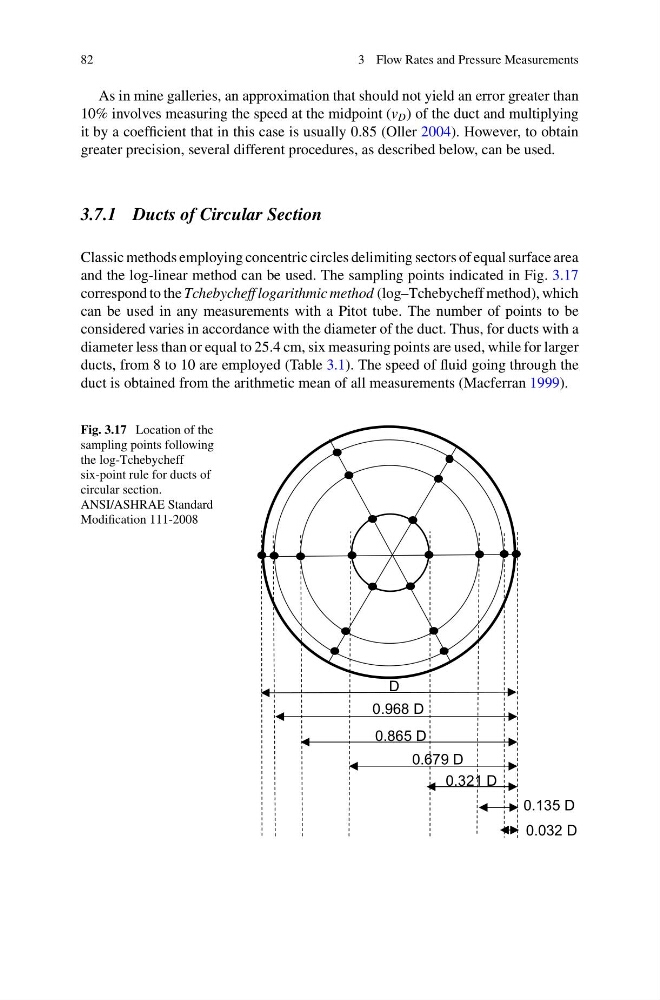
and the log-linear method can be used. The sampling points indicated in Fig. 3.17
correspond to the Tchebycheff logarithmic method (log–Tchebycheff method), which
can be used in any measurements with a Pitot tube. The number of points to be
considered varies in accordance with the diameter of the duct. Thus, for ducts with a
diameter less than or equal to 25.4 cm, six measuring points are used, while for larger
ducts, from 8 to 10 are employed (Table 3.1). The speed of fluid going through the
duct is obtained from the arithmetic mean of all measurements (Macferran 1999).
Fig. 3.17 Location of the
sampling points following
the log-Tchebycheff
six-point rule for ducts of
circular section.
ANSI/ASHRAE Standard
Modification 111-2008
0.032 D
0.135 D
0.321 D
0.679 D
0.865 D
0.968 D
D
3 Flow Rates and Pressure Measurements
As in mine galleries, an approximation that should not yield an error greater than
10% involves measuring the speed at the midpoint (v D ) of the duct and multiplying
it by a coefficient that in this case is usually 0.85 (Oller 2004). However, to obtain
greater precision, several different procedures, as described below, can be used.
3.7.1 Ducts of Circular Section
Classic methods employing concentric circles delimiting sectors of equal surface area
and the log-linear method can be used. The sampling points indicated in Fig. 3.17
correspond to the Tchebycheff logarithmic method (log–Tchebycheff method), which
can be used in any measurements with a Pitot tube. The number of points to be
considered varies in accordance with the diameter of the duct. Thus, for ducts with a
diameter less than or equal to 25.4 cm, six measuring points are used, while for larger
ducts, from 8 to 10 are employed (Table 3.1). The speed of fluid going through the
duct is obtained from the arithmetic mean of all measurements (Macferran 1999).
Fig. 3.17 Location of the
sampling points following
the log-Tchebycheff
six-point rule for ducts of
circular section.
ANSI/ASHRAE Standard
Modification 111-2008
0.032 D
0.135 D
0.321 D
0.679 D
0.865 D
0.968 D
D