

76
3 Flow Rates and Pressure Measurements
v m = 0.083 v D + 0.313 v C + 0.286 v B + 0.282 v A
(3.8)
The configuration above is complex to perform in practice, for this reason homothetic curves can be equally spaced (e.g. 60 cm), and the approximation of Eq. 3.9
can be used:
v m = 0.07v D + 0.3(v A + v B + v C )
(3.9)
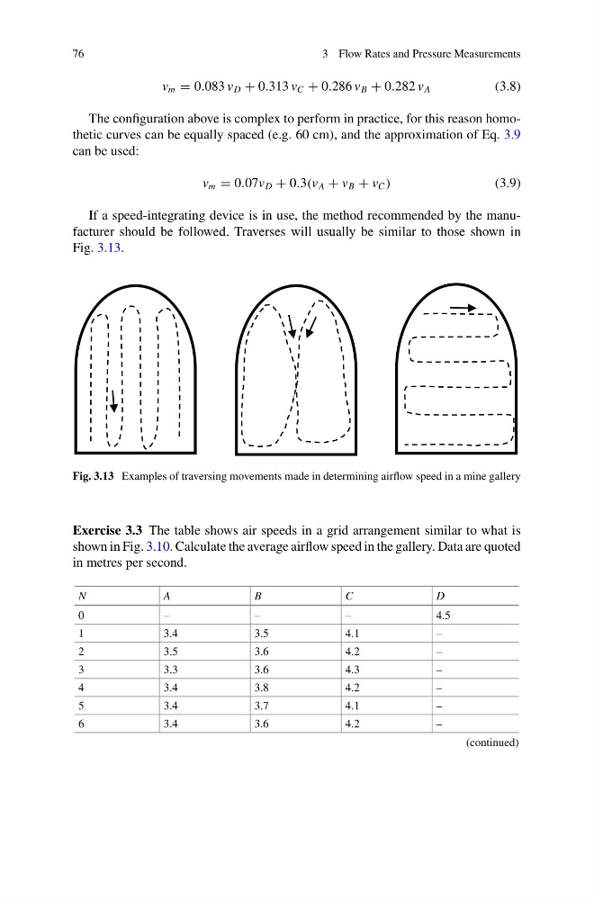
If a speed-integrating device is in use, the method recommended by the manufacturer should be followed. Traverses will usually be similar to those shown in
Fig. 3.13.
Fig. 3.13 Examples of traversing movements made in determining airflow speed in a mine gallery
Exercise 3.3 The table shows air speeds in a grid arrangement similar to what is
shown in Fig. 3.10. Calculate the average airflow speed in the gallery. Data are quoted
in metres per second.
N
A
B
C
D
0
–
–
–
4.5
1
3.4
3.5
4.1
–
2
3.5
3.6
4.2
–
3
3.3
3.6
4.3
–
4
3.4
3.8
4.2
–
5
3.4
3.7
4.1
–
6
3.4
3.6
4.2
–
(continued)
3 Flow Rates and Pressure Measurements
v m = 0.083 v D + 0.313 v C + 0.286 v B + 0.282 v A
(3.8)
The configuration above is complex to perform in practice, for this reason homothetic curves can be equally spaced (e.g. 60 cm), and the approximation of Eq. 3.9
can be used:
v m = 0.07v D + 0.3(v A + v B + v C )
(3.9)
If a speed-integrating device is in use, the method recommended by the manufacturer should be followed. Traverses will usually be similar to those shown in
Fig. 3.13.
Fig. 3.13 Examples of traversing movements made in determining airflow speed in a mine gallery
Exercise 3.3 The table shows air speeds in a grid arrangement similar to what is
shown in Fig. 3.10. Calculate the average airflow speed in the gallery. Data are quoted
in metres per second.
N
A
B
C
D
0
–
–
–
4.5
1
3.4
3.5
4.1
–
2
3.5
3.6
4.2
–
3
3.3
3.6
4.3
–
4
3.4
3.8
4.2
–
5
3.4
3.7
4.1
–
6
3.4
3.6
4.2
–
(continued)