

3.5 Estimating the Section of a Gallery
71
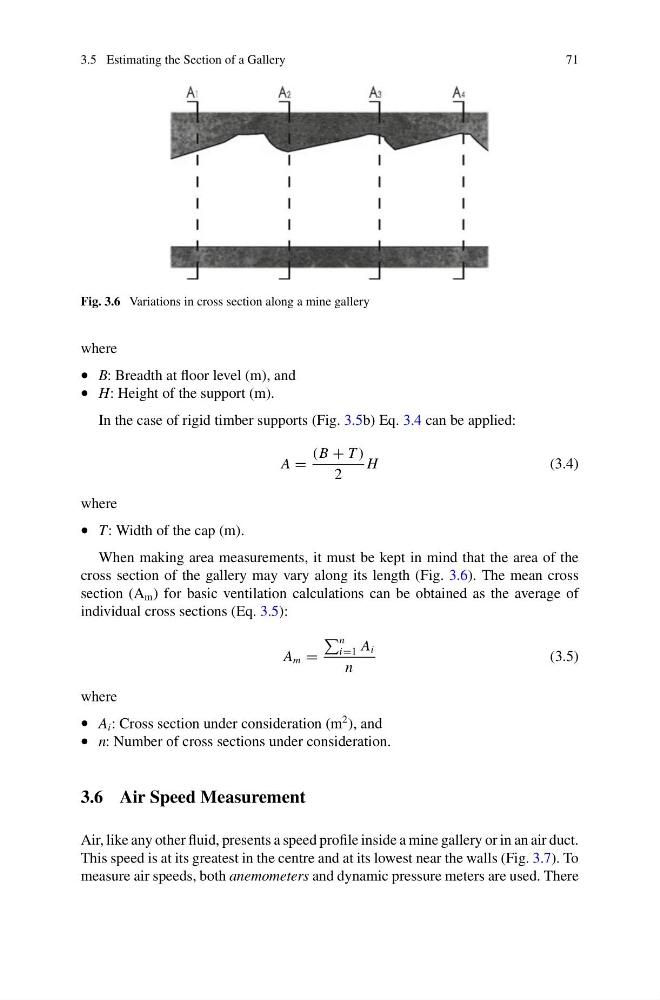
Fig. 3.6 Variations in cross section along a mine gallery
where
• B: Breadth at floor level (m), and
• H: Height of the support (m).
In the case of rigid timber supports (Fig. 3.5b) Eq. 3.4 can be applied:
A =
(B + T )
2
H
(3.4)
where
• T: Width of the cap (m).
When making area measurements, it must be kept in mind that the area of the
cross section of the gallery may vary along its length (Fig. 3.6). The mean cross
section (A m ) for basic ventilation calculations can be obtained as the average of
individual cross sections (Eq. 3.5):
A m =
n
i=1 A i
n
(3.5)
where
• A i : Cross section under consideration (m
2 ), and
• n: Number of cross sections under consideration.
3.6 Air Speed Measurement
Air, like any other fluid, presents a speed profile inside a mine gallery or in an air duct.
This speed is at its greatest in the centre and at its lowest near the walls (Fig. 3.7). To
measure air speeds, both anemometers and dynamic pressure meters are used. There
71
Fig. 3.6 Variations in cross section along a mine gallery
where
• B: Breadth at floor level (m), and
• H: Height of the support (m).
In the case of rigid timber supports (Fig. 3.5b) Eq. 3.4 can be applied:
A =
(B + T )
2
H
(3.4)
where
• T: Width of the cap (m).
When making area measurements, it must be kept in mind that the area of the
cross section of the gallery may vary along its length (Fig. 3.6). The mean cross
section (A m ) for basic ventilation calculations can be obtained as the average of
individual cross sections (Eq. 3.5):
A m =
n
i=1 A i
n
(3.5)
where
• A i : Cross section under consideration (m
2 ), and
• n: Number of cross sections under consideration.
3.6 Air Speed Measurement
Air, like any other fluid, presents a speed profile inside a mine gallery or in an air duct.
This speed is at its greatest in the centre and at its lowest near the walls (Fig. 3.7). To
measure air speeds, both anemometers and dynamic pressure meters are used. There